
Access Port

a technology of access port and stent, which is applied in the direction of catheter, infusion needle, trocar, etc., can solve the problems of kinking of the conduit, poor sealing around the catheter, and inability to achieve a good seal around the catheter, so as to reduce the risk of kinking the conduit and facilitate the opening

Active Publication Date: 2009-07-30
COLOPLAST AS
View PDF12 Cites 69 Cited by
  • Summary
  • Abstract
  • Description
  • Claims
  • Application Information

AI Technical Summary

Benefits of technology

[0010]One object of the present invention is to provide a drain access port being capable of securing a leak proof seal between a conduit and a partition wall.
[0012]Yet another object of the present invention is to provide an access port that is discrete, flexible and easy to use.
[0014]Yet another object is to provide a closure of an access port that may easily be opened without use of tools.
[0015]Still another object is to provide is to provide an access port that reduces the risk of kinking the conduit.

Problems solved by technology

Several problems may be associated with these access ports: Flexibility allowing the conduit to enter different positions under control, adapting the size or the aperture for the conduit to fit different conduit diameters, attachment to the surface and avoiding leakage.
If the user tries to access the port with a catheter form the other side, there is a risk of separating the two parts during use.
In the operation the operator has a risk of cutting the opening to big, this will give a poor seal around the catheter.
Furthermore after having adjusted the nipple portion to a certain catheter size, good seal around a smaller catheter cannot be achieved.
The limited elasticity or stretchability of the material jeopardizes the introduction of anything into the drains access port that is a considerably bigger than the aperture that the user have cut from start.
The rigidity of this clamping portion increases the risk of kinking the conduit (e.g. a catheter), because it is made of two rigid injection molded parts and thus not flexible.
However, the material is not flexible enough to introduce something into the drain access port that is just a little bigger than the opening the user has cut from start as the flexibility of the material is to low.
This makes it difficult to insert something slightly bigger than the opening created by the cut.
Due to that it feels more difficult to insert a catheter that is just slightly bigger than the opening, the user have tendency to cut the opening even bigger, increasing the risk of poor sealing.
The above-mentioned devices need a (sterile) scissor or other cutting instrument for making a hole and it may be a problem to have such sterile scissors available.
Cuffing with non-sterile scissors may lead to infection of the site.

Method used


Image

  • Access Port
  • Access Port
  • Access Port

Examples


examples

[0098]The position and dimensions of the sleeve portion is important in order to obtain an optimum sealing against a conduit. Different samples have been tested in order to identify the critical properties.

[0099]The material for the access port has been stored at 23° C. or 40° C. for 15 month at 100% humidity and tested afterwards up to a pressure on 0.03 bar.

[0100]The samples have been tested for providing perfect sealing under conditions similar to use on a fistula / wound collection pouch, for 3 days at 100% humidity at 40° C. It is important to test the samples under such conditions, as these reflect the condition the access port may be used under. Catheters or conduits may stay inserted for days, and a port that may be leakage proof the first day, may be influenced by the temperature, stress and humidity and thus become less leakage proof over time.

[0101]The tests showed that most materials would change their properties over time and temperature. An aperture designed for easy acc...

example a

Importance of the Positioning of the Sleeve

[0103]An access port with a simple design as illustrated in FIGS. 7a and 7b was prepared from SEBS. All dependent on the size of the starting aperture in the access port and the size of the inserted catheter the test result may vary slightly. Test has shown that most very flexible materials will show same result even if a much bigger catheter is inserted through same small starting aperture.

[0104]In this example the wall thickness of the sleeve is 0.6 mm and the sleeve length is 8 mm and having a starting aperture of 5 mm. Stored for 3 days at 100% humidity at 40° C. with a CH18 (6 mm) catheter inserted in the access port.

TABLE 1SleeveTest atTest atTest atposition0.050.15 bar0.3 barUpwardsRisk of leakageLeakageLeakageDownwardsNo leakNo leakNo leakageor minimalrisk of leakage

[0105]Results with the sleeve portion positioned downwards—a significant improvement of the sealing, same result can be achieved even when rotating the catheter as long ...

example b

Attempt to Compensate for the Change in Material Properties—with Designs where the Sleeve is Positioned Upwards

[0107]In FIGS. 8a and 8b is shown solutions based on use of fixation means, which can fixate the access port to the catheter, preventing the catheter in moving upwards and maintaining perfect sealing by obtaining a constant pressure between the catheter walls and the sleeve of the access port.

[0108]The solution involves either a repositionable string, cord, clamp, tape or other fixations means (12). It is preferred that the fixation means can be tightened all around the catheter.


PUM


Abstract

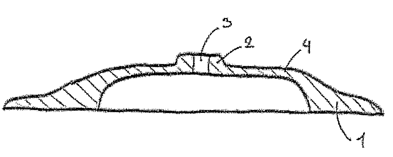
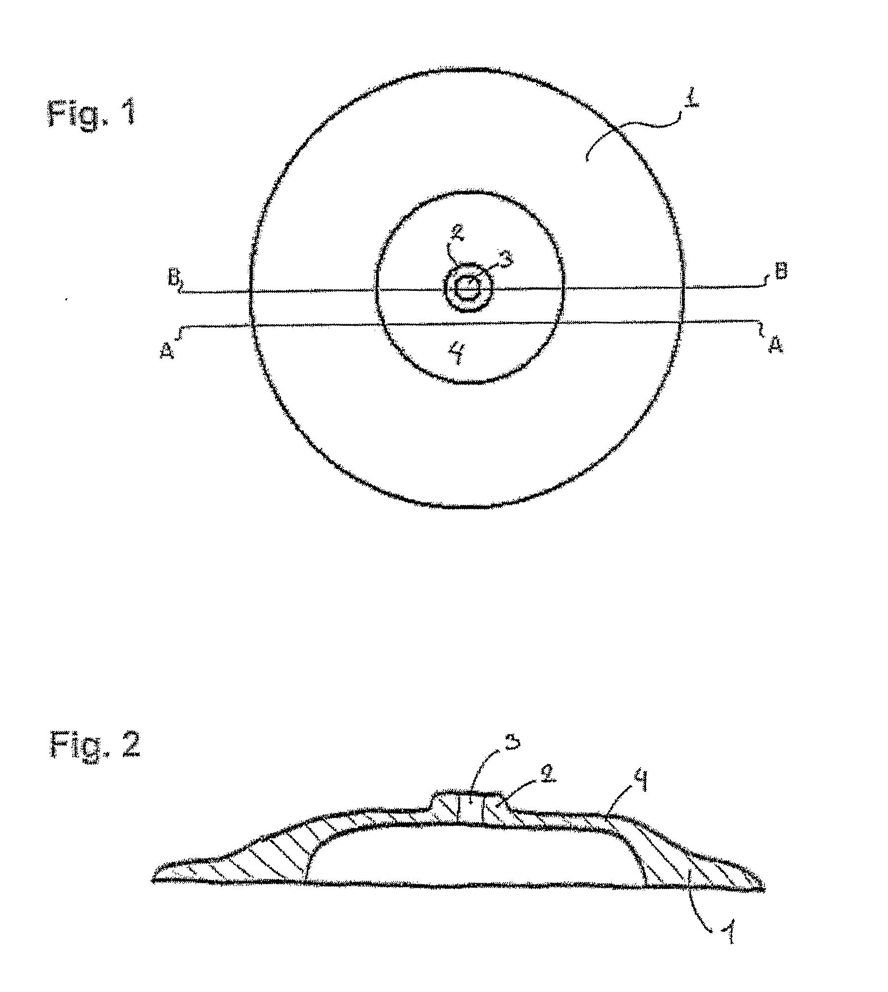
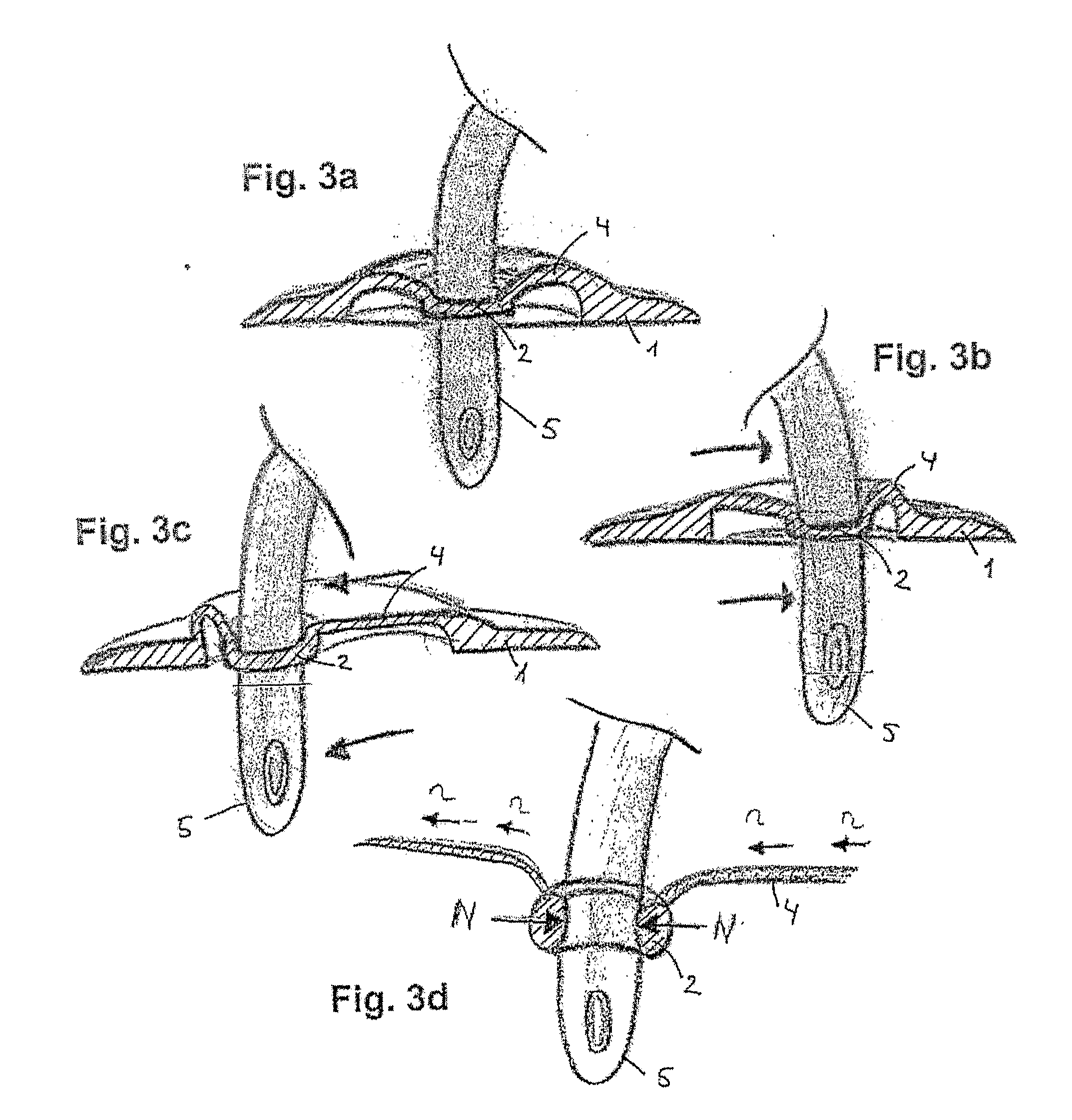
An access port for enabling passage of a conduit through a partition wall, said port comprising three portions, a sleeve portion surrounding an aperture for receiving a conduit there through, a flange portion for attachment to the partition wall, said flange portion encircles the sleeve portion and has a greater diameter than the sleeve portion, and a membrane portion connecting the flange portion and the sleeve portion. The port may be suitable for, in a leak-proof manner, passing a catheter or drain tube through the wall of a medical device such as a wound care device or a drainage bag.

Description

BACKGROUND OF THE INVENTION[0001]1. Field of the Invention[0002]The invention relates to an access port for providing a leak proof seal between a conduit and a partition wall such as a film layer of a medical device or the skin.[0003]2. Description of the Related Art[0004]It is often desired to lead a conduit, such as a drain tube, catheter, trocar or the like through a barrier, such as a flexible film, the wall of an ostomy bag or the skin surface, e.g. laparoscopy in a leak proof manner. Access ports for such purposes are well known in the art. Several problems may be associated with these access ports: Flexibility allowing the conduit to enter different positions under control, adapting the size or the aperture for the conduit to fit different conduit diameters, attachment to the surface and avoiding leakage.[0005]In U.S. Pat. No. 5,215,531 is disclosed a cannula skirt for stabilizing and restraining the movement of a laparoscopic cannula as well as providing a leakage tight seal...

Claims


Application Information

Patent Timeline
IPC IPC(8): A61M25/02
CPCA61B17/3462A61B2017/3407A61M2025/0246A61M25/02A61M39/06A61B2017/3492
Inventor HANSEN, MICHAELMUELLEJEANS, PETERJENSEN, BENT HALL
Owner COLOPLAST AS
Learn More