
Method & apparatus for arthroscopic biceps tenodesis

Inactive Publication Date: 2009-07-30
THE LONNIE & SHANNON PAULOS TRUST AS AMENDED & RESTATED
View PDF8 Cites 21 Cited by
  • Summary
  • Abstract
  • Description
  • Claims
  • Application Information

AI Technical Summary

Benefits of technology

[0014]Principal objects of the invention are to provide biceps tenodesis that is safe, effective and reproducible. Other objects are to provide a procedure that can be performed quickly and without the need for specialized equipment. At most, a very simple, easily used anchor button may be employed as the wedging structure placed at the proximal end of the long head of the biceps tendon. Accessory incisions are not required and operative time and costs are reduced in comparison with other possible procedures.
[0016]It is believed that the procedure of creating and using a wedging structure in biceps tenodesis can successfully improve pain control, while still resulting in minimal cosmetic deformity and / or loss of strength of the bicep.
[0022]The clamshell type button of the invention includes a top section and a bottom section connected at one end of the football shaped body by a hinge and with locking holding means at the opposite locking end of the body to secure the top and bottom sections together in a clamping configuration. A hole through which a traction suture is passed is formed in the hinge end of the bottom section. A rack having spaced teeth along its length is formed at the locking end of the bottom section. The rack pivots at the locking end of the bottom section to extend into and through an opening formed at the locking end of the top section. A shaped locking flange formed to extend into the opening at the locking end of the top section is sufficiently flexible to allow insertion of the rack into the opening and, because of the shape prevents withdrawal of the inserted rack. Once the rack is pushed into the opening the top and bottom sections are securely locked together. The long head end of the biceps tendon being repaired is positioned between the top and bottom sections and when the top and bottom portions are locked together, the clamshell type button is firmly secured to the tendon.
[0023]The outer surfaces of the top and bottom sections are preferably made “rough” to enhance wedging during use. In addition, staggered clamping ribs on the engaging surfaces of the top and bottom sections are pushed into the tendon to further insure secure attachment of the clamshell type button to the tendon and to prevent sliding of the button along and off the tendon.

Problems solved by technology

Such open techniques, however, have potential major disadvantages since morbidity may be incurred through necessary accessory incisions.
Disadvantages are the increased operative time required and, currently, a lack of knowledge of the long term success of the treatments.
Unfortunately, the interference screw causes tendon damage and may amputate the tendon at the edge of the bone panel.
It is also becomes very difficult to even place sutures that will hold the tendon during healing.
The healing of a sutured tendon takes much longer and requires protection, with a resultant loss of motion and with a potential need for further surgery that will include follow-up scope evaluation and manipulation of the tendon.

Method used


Image

  • Method & apparatus for arthroscopic biceps tenodesis
  • Method & apparatus for arthroscopic biceps tenodesis
  • Method & apparatus for arthroscopic biceps tenodesis

Examples


Embodiment Construction

[0041]Referring Now to the Drawings

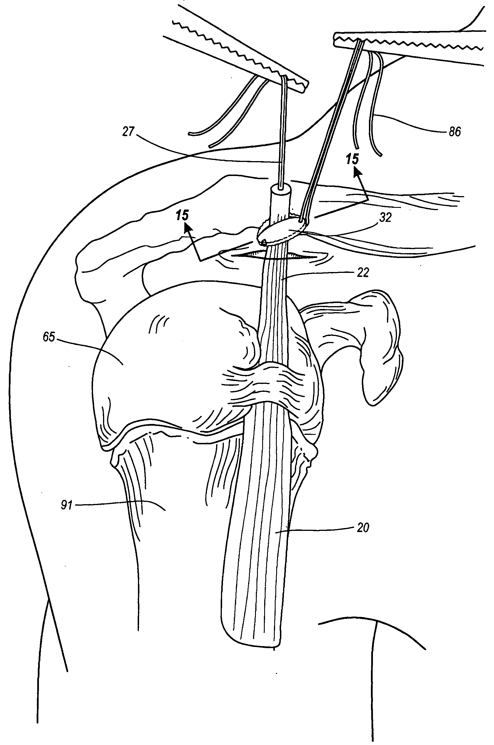
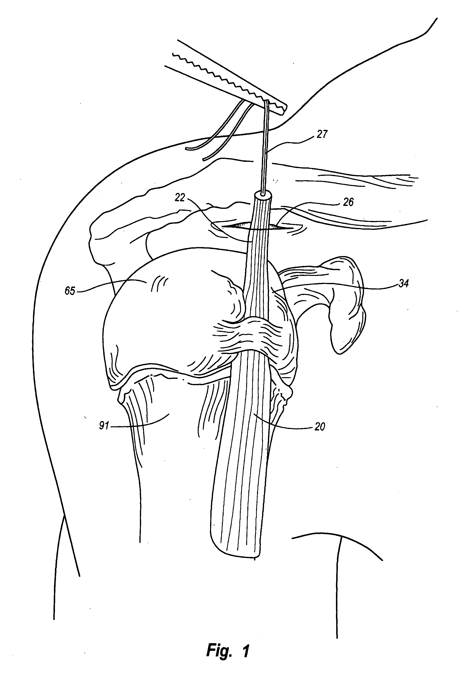
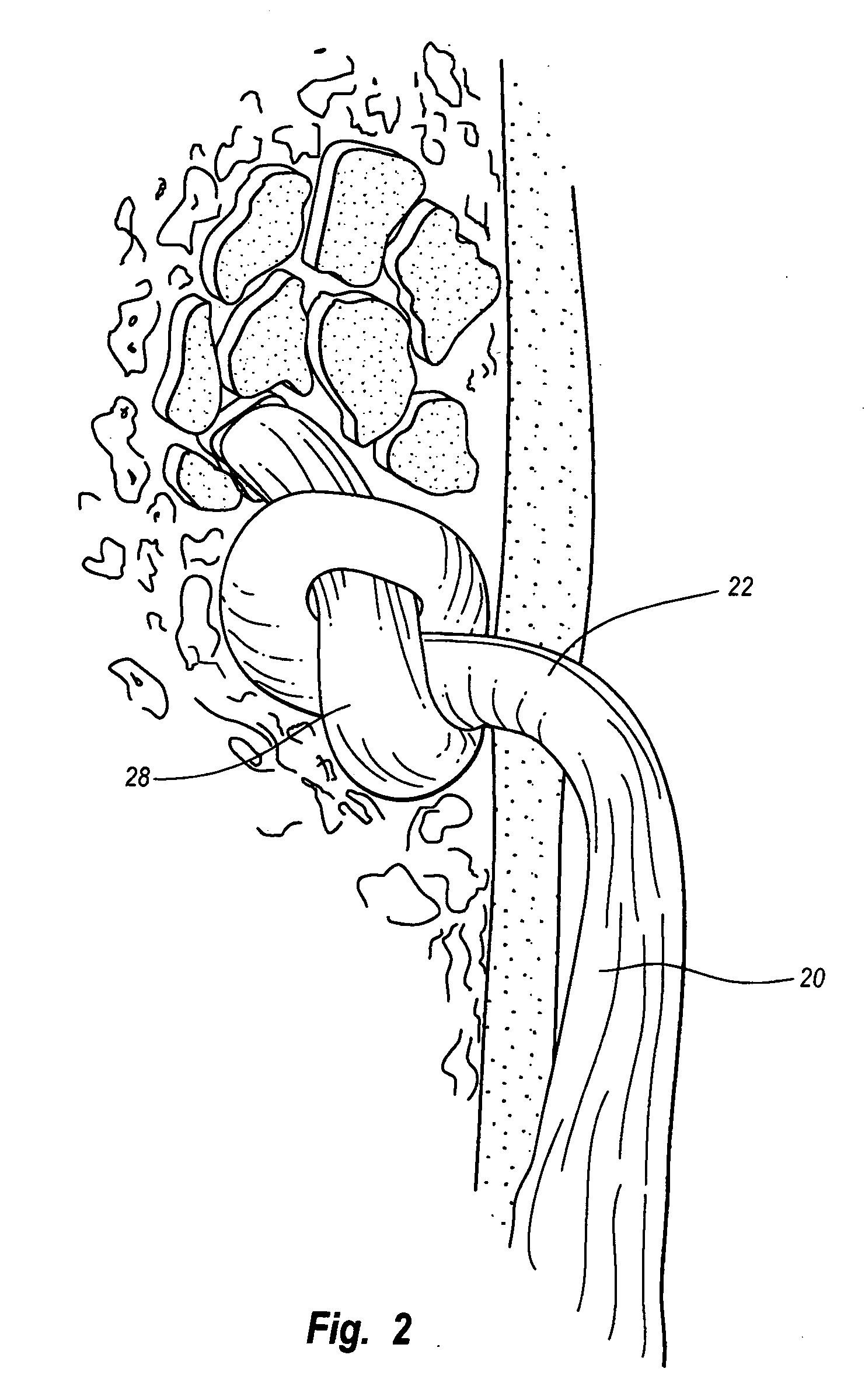
[0042]In a preferred embodiment, the process of wedge tenodesis disclosed involves the steps of (1) arthroscopically determining that a repair of a biceps tendon 20 is necessary using conventional arthroscopic procedures, and that a tenodesis is the best procedure for making such repair; (2) arthroscopically separating the head of the biceps tendon from the superior labium; (3) pulling the separated end 22 of the biceps tendon 20 through a portal 26 with a suture 27 and trimming the end 22 of the tendon 20; (4) selecting a wedge to be used from a tied knot wedge 28, FIG. 2, a sutured knot wedge 30, FIG. 3, or a clamp wedge 32, FIG. 9, to be affixed to the separated end 22 of the tendon 20; (5) affixing the selected wedge to the separated end 22 of the tendon 20; and (6) positioning the selected wedge in the bicipital groove 34 of the patient while allowing the biceps tendon 20 to retract within the bicipital groove 34 until held by engagement of th...


PUM


Abstract

A method and apparatus for arthroscopic biceps tenodesis wherein the method involves arthroscopically determining that biceps tenodesis is desirable; arthroscopically separating the long head of the biceps tendon from bone attachment; creating and placing a wedge at the proximal end of the long head of the biceps tendon; and allowing the tendon to slide through the glenohumeral joint and the wedge structure to be wedged in the bicipital groove and wherein the apparatus includes a clamshell type, button wedge having a football shaped body with top and bottom portions hinged at one end and with locking structure at an opposite end to lock the top and bottom portions together, such that staggered ribs on the top portion and bottom portion grip top and bottom surfaces of the long head of the tendon when the top and bottom portions of the button wedge are clamped together.

Description

CROSS-REFERENCE TO RELATED APPLICATIONS[0001]Not Applicable.STATEMENT REGARDING FEDERALLY SPONSORED RESEARCH OR DEVELOPMENT[0002]Not Applicable.REFERENCE TO MICROFICHE APPENDIX[0003]Not Applicable.BACKGROUND OF THE INVENTION[0004]1. Field of the Invention[0005]This invention relates to a method and apparatus for performing an arthroscopic biceps tenodesis.[0006]2. Description of the Prior Art[0007]With the increased use of systematic arthroscopic shoulder examinations and arthroscopic procedures, pathology of the long head of the biceps tendon has become more frequently identified. Biceps tendon pathology is found in a wide variety of shoulder conditions, ranging from instability to rotator cuff disorders and primary biceps tendon pathology. Prior to arthroscopic viewing of the glenohumeral joint and the detailed examination that it affords, the long head of the biceps was rarely visualized surgically and biceps tendon pathology was not recognized until in later stages. Arthroscopy ...

Claims


Application Information

Patent Timeline
IPC IPC(8): A61F2/08A61B19/00
CPCA61B17/0401A61F2/0805A61B2017/0417A61B17/122
Inventor PAULOS, LONNIE E.
Owner THE LONNIE & SHANNON PAULOS TRUST AS AMENDED & RESTATED
Learn More