Device and method for detecting a leak in a cylinder of an internal combustion engine

a technology of internal combustion engine and leak detection, which is applied in the direction of machines/engines, fluid tightness measurement, instruments, etc., can solve the problems of problematic procedures and suffer diagnostic quality, and achieve simple and robust, weaker crankshaft braking

Active Publication Date: 2009-07-30
ROBERT BOSCH GMBH
View PDF2 Cites 7 Cited by
  • Summary
  • Abstract
  • Description
  • Claims
  • Application Information

AI Technical Summary

Benefits of technology

[0008]The present invention is based on the knowledge that linking the time intervals before and after the top dead center of the monitored cylinder provides a simple means of improving the detection of a leak in the cylinder of the internal combustion engine. In particular, this approach makes use of the interdependency by which the compression pressure and the expansion pressure in the monitored cylinder vary when a leak occurs in the cylinder. In doing this, a linkage of the segment travel times which the crankshaft requires to pass a preset angle segment before and after the ITDC of the piston supplies a much better result with regard to the detection of leaks in the cylinder than does the separate evaluation of segment travel times only before or only after the ITDC. At the same time, this linkage of segment travel times may also provide a more robust evaluation, in particular when sensor wheel tolerances occur, since the approach according to the present invention may slightly compensate for these tolerances because two angle segments are evaluated for each cylinder. The approach according to the present invention therefore provides the advantage of enabling the diagnostic quality to be substantially improved by algorithmically preparing and linking the already available signals.
[0023]The present invention also includes a computer program for carrying out the aforementioned method when the computer program is run on a data processing system. This makes it possible to use the on-board computers commonly found in vehicles having internal combustion engines for evaluating the determination of a leak in a cylinder in a test mode.

Problems solved by technology

However, a procedure of this type is problematic if tolerances occur in the measuring teeth of a sensor wheel which is attached to the crankshaft and whose measuring teeth are used to determine the time intervals which the crankshaft requires to pass the corresponding angle segments before and after the ITDC.
Under some circumstances, the tooth times to be evaluated are corrupted by these sensor wheel tolerances to such a great extent that errors may be incorrectly detected on the cylinders or, alternatively, at high tolerances, a very high error detection threshold must be selected, which causes the diagnostic quality to suffer in the event of an error.

Method used


Image

  • Device and method for detecting a leak in a cylinder of an internal combustion engine
  • Device and method for detecting a leak in a cylinder of an internal combustion engine
  • Device and method for detecting a leak in a cylinder of an internal combustion engine

Examples


Embodiment Construction

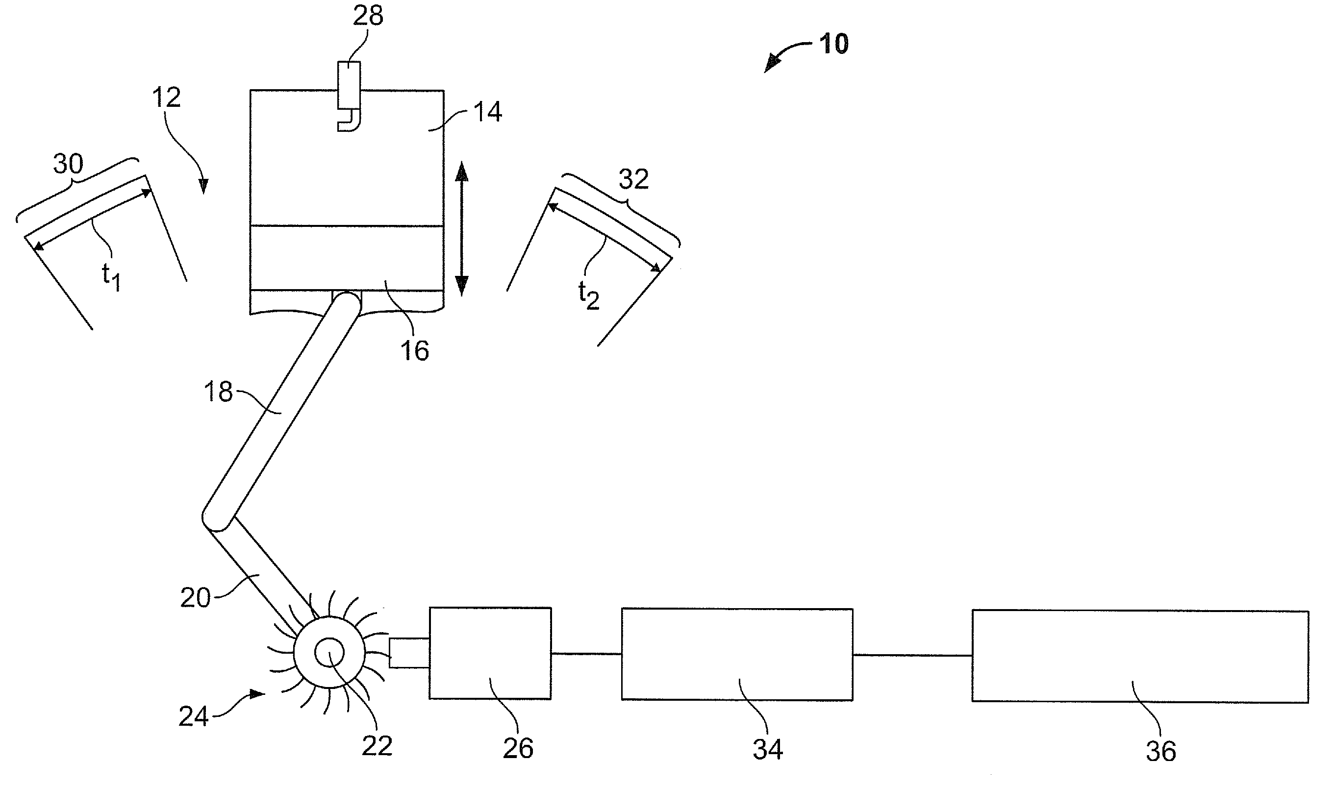
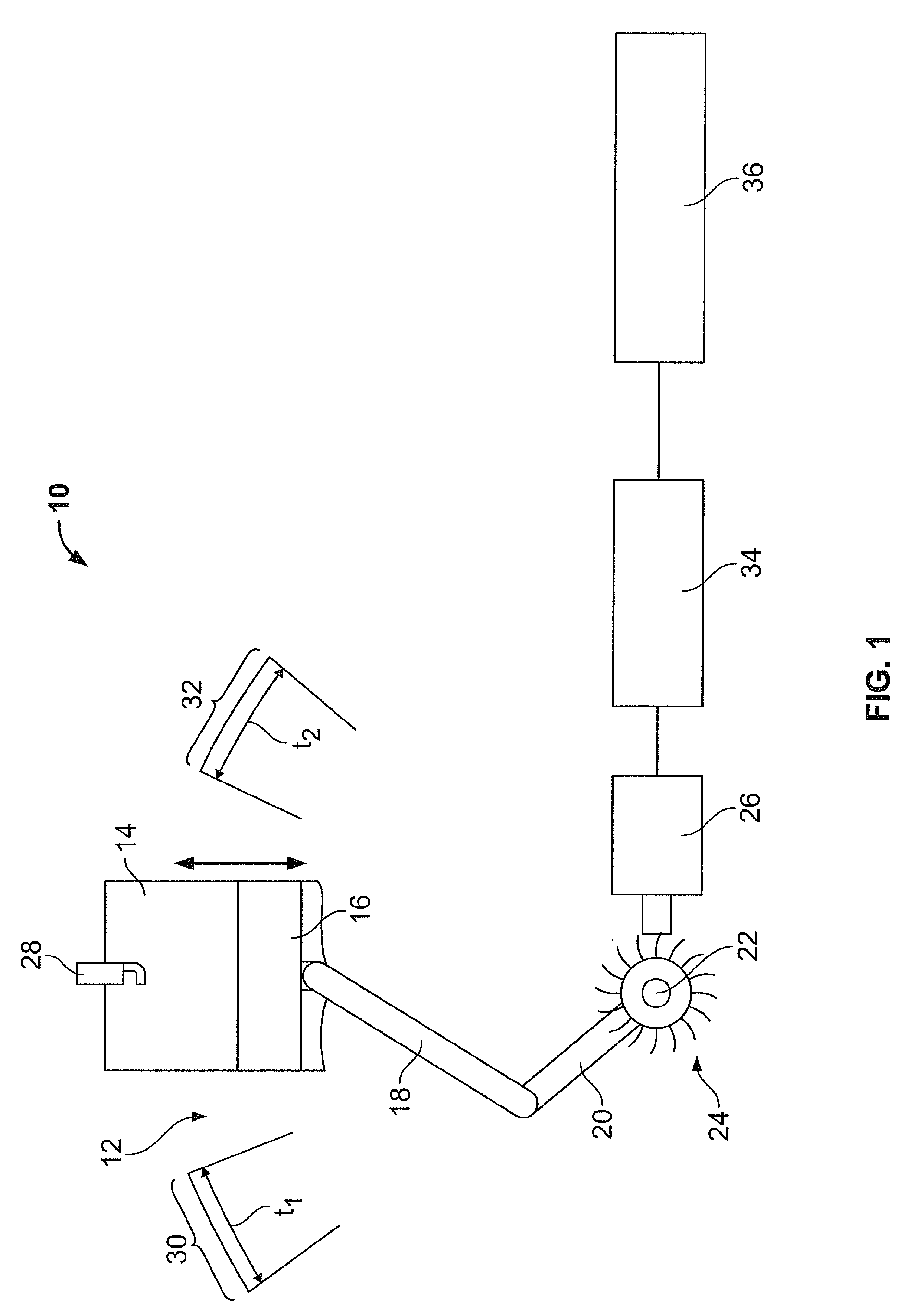
[0029]FIG. 1 shows a block diagram which illustrates the principle structure of an exemplary embodiment of device 10 according to the present invention in interaction with the components of an internal combustion engine 12. Internal combustion engine 12 includes a cylinder 14 in which a piston 16 is able to move up and down, this piston, in turn, being attached to a crankshaft 20 by a connecting rod 18. Connecting rod 18 is attached to a segment which is offset from rotation axis 22 of crankshaft 20. Internal combustion engine 12 usually includes multiple cylinders which have a structure similar to that of cylinder 14, but which are not shown in FIG. 1 for the purpose of better clarity. Crankshaft 20 has a sensor wheel 24 on a segment which lies on the rotation axis of crankshaft 20. This sensor wheel 24 has sensor wheel teeth, which may be used to determine the instantaneous rotation angle of crankshaft 20 with the aid of a position detecting unit 26. To determine the absolute posi...


PUM


Abstract

A device for detecting a leak in a cylinder of an internal combustion engine, the internal combustion engine including a piston in the cylinder, the piston being attached to a crankshaft, includes a time interval determining unit which is designed to determine a first time interval in which the crankshaft passes a preset first angle segment before reaching the ignition top dead center of the piston in the cylinder, and to determine a second time interval in which the crankshaft passes a preset second angle segment after reaching the ignition top dead center of the piston in the cylinder, and a cylinder leak determining unit which is designed to detect a leak in the cylinder as a function of the first time interval and as a function of the second time interval.

Description

FIELD OF INVENTION[0001]The present invention relates to a device for detecting a leak in a cylinder of an internal combustion engine as well as to a method for detecting a leak in a cylinder of an internal combustion engine.BACKGROUND INFORMATION[0002]Previous approaches are known for establishing compression losses at individual cylinders of an internal combustion engine by evaluating a crankshaft sensor signal. In doing this, certain segment travel times are measured and evaluated in the control unit by measuring teeth of a crankshaft sensor wheel, making it possible to infer the time interval that a crankshaft requires to pass a predefined angle segment. If compression losses occur in the monitored cylinder, it takes the crankshaft less time to pass an angle segment before the ignition top dead center of the piston in the cylinder than would be the case when the closure or sealing of the cylinder is error-free (i.e., “okay”). This dead center is also referred to below as “ITDC” ...

Claims


Application Information

Patent Timeline
Patent Type & Authority Applications(United States)
IPC IPC(8): G01M3/04
CPCG01M15/046
Inventor BETHMANN, ANDREAS
Owner ROBERT BOSCH GMBH
Why Eureka
Try Eureka