Methods and apparatus for operating gas turbine engine systems

a gas turbine engine and gas turbine technology, applied in the direction of engine starters, turbine/propulsion engine ignition, transmission monitoring, etc., can solve the problems of unsatisfactory linear flow command, inability to properly linearize flow command across loading range, and undesirable non-linearity of drooping, so as to facilitate a relatively large variation in fuel composition

Inactive Publication Date: 2009-08-06
GENERAL ELECTRIC CO
View PDF26 Cites 42 Cited by
  • Summary
  • Abstract
  • Description
  • Claims
  • Application Information

AI Technical Summary

Benefits of technology

[0007]In one embodiment, a gas turbine engine includes an electrical generator configured to provide electrical energy to a load, a gas turbine engine including at least one combustor including a plurality of fuel injection points configured to receive a flow of fuel from a plurality of corresponding flow control devices, and a fuel control system. The fuel control system includes a plurality of sensors positioned about the gas turbine engine system and configured to measure at least one parameter associated with the sensor and a processor. The processor is programmed to receive a signal from at least one of the plurality of sensors indicative of a composition of the fuel, using a flow model and the at least one signal, determine the physical properties of a fuel at an inlet to the flow control devices, determine a corresponding correction to a gas fuel flow gain using the determined physical properties, and automatically control fuel delivery as well as fuel split between the fuel injection points on the combustor using the adjusted flow gain to facilitate permitting a relatively large variation in the fuel composition for use in the gas turbine engine.

Problems solved by technology

The inputs used to calculate the flow gain are dependant on fuel constituents and the application of this flow conversion technique is limited to applications with fairly constant fuel properties.
Therefore, without correcting for changes in fuel properties the flow gain will not properly linearize the flow command across the loading range.
This can lead to an undesirable droop non-linearity and can cause load transients when fuel properties change significantly, for example during fuel transfers or following large changes in fuel temperature.
However, when power augmentation systems are used, like a fuel moisturization system, the magnitude of the changes in fuel physical properties is significant, and a new technique is needed to accurately calculate the correct flow gain.

Method used


Image

  • Methods and apparatus for operating gas turbine engine systems
  • Methods and apparatus for operating gas turbine engine systems
  • Methods and apparatus for operating gas turbine engine systems

Examples


Embodiment Construction

[0013]While the methods and apparatus are herein described in the context of a gas turbine engine used in an industrial environment, it is contemplated that the method and apparatus described herein may find utility in other combustion turbine systems applications including, but not limited to, turbines installed in aircraft. In addition, the principles and teachings set forth herein are applicable to gas turbine engines using a variety of combustible fuels such as, but not limited to, natural gas, liquefied natural gas, gasoline, kerosene, diesel fuel, and jet fuel. The description herein below is therefore set forth only by way of illustration, rather than limitation.

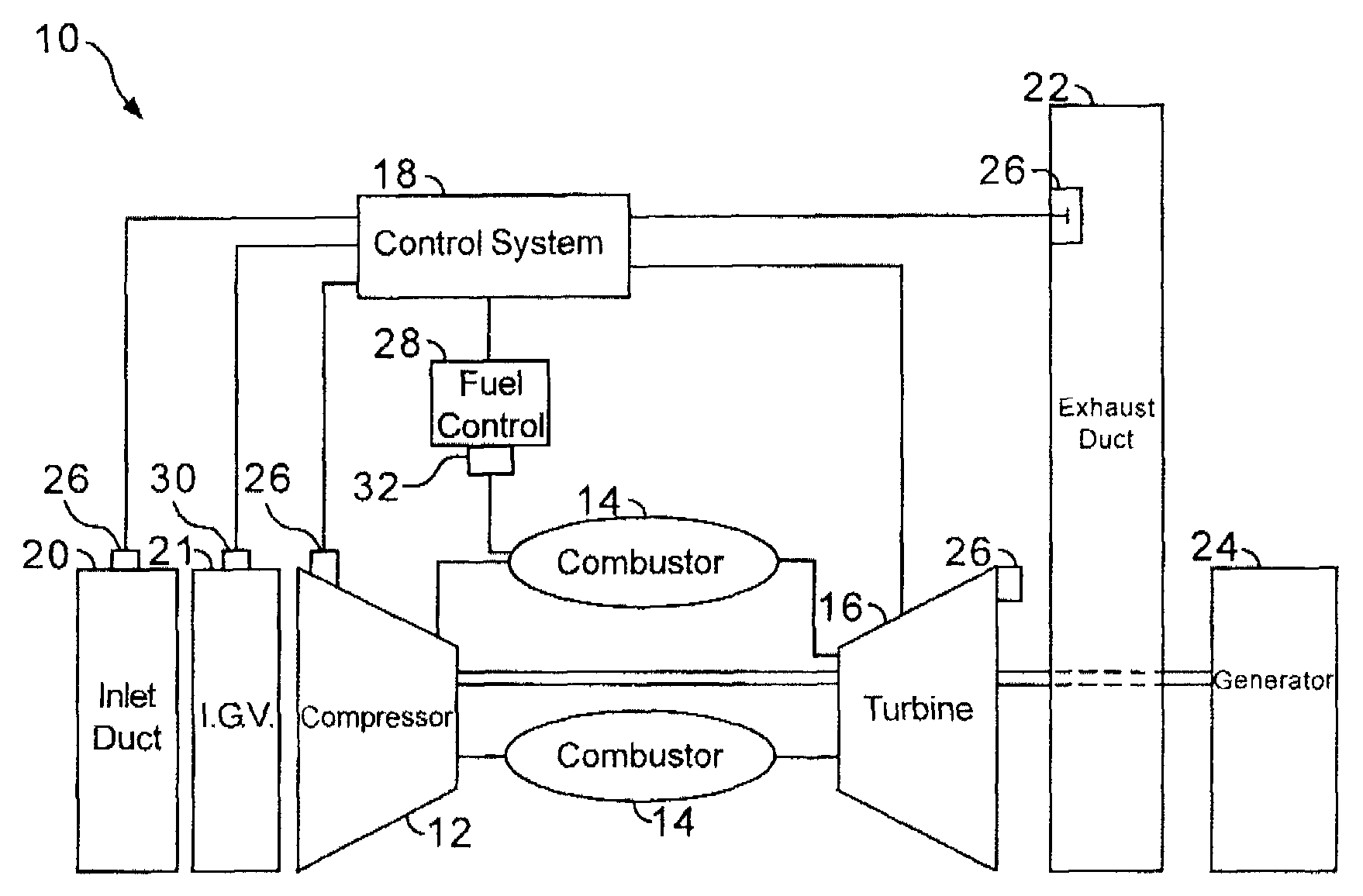
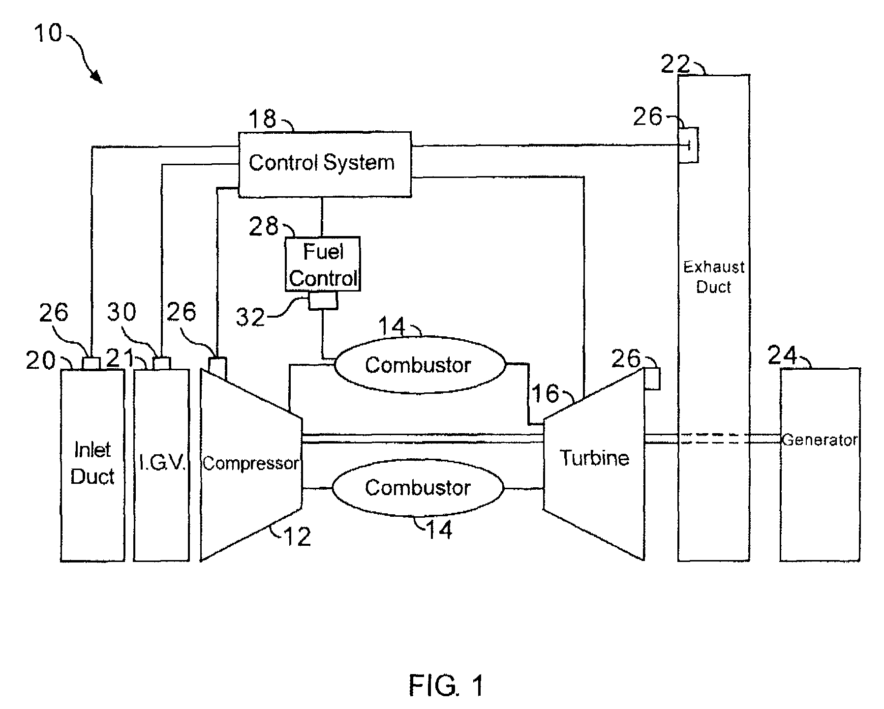
[0014]FIG. 1 is a schematic diagram of a gas turbine engine system 10 including a compressor 12, a combustor 14, a turbine 16 drivingly coupled to compressor 12, and a control system 18. An inlet duct 20 channels ambient air to the compressor. In one embodiment, injected water and / or other humidifying agent is also ch...


PUM


Abstract

Methods and systems for operating a gas turbine engine system are provided. The system includes a fuel control system. The fuel control system includes a plurality of sensors positioned about the gas turbine engine system and configured to measure at least one parameter associated with the sensor, and a processor programmed to receive a signal from at least one of the plurality of sensors indicative of a composition of the fuel. The processor is further programmed to determine the physical properties of a fuel at an inlet to the flow control devices using a flow model and the at least one signal, determine a corresponding correction to a gas fuel flow gain using the determined physical properties, and automatically control fuel delivery as well as fuel split between the fuel injection points on the combustor using the adjusted flow gain to facilitate permitting a relatively large variation in the fuel composition for use in the gas turbine engine.

Description

BACKGROUND OF THE INVENTION[0001]This invention relates generally to gas turbine engines, and more particularly, to methods and apparatus for controlling the operation of gas turbine engines.[0002]Gas turbine engines typically include a compressor section, a combustor section, and at least one turbine section. The compressor compresses air, which is mixed with fuel and channeled to the combustor. The mixture is then ignited generating hot combustion gases. The combustion gases are channeled to the turbine, which extracts energy from the combustion gases for powering the compressor, as well as producing useful work to power a load, such as an electrical generator, or to propel an aircraft in flight.[0003]Gas turbine engines operate in many different operating conditions, and combustor performance facilitates engine operation over a wide range of engine operating conditions. Controlling combustor performance may be used to improve overall gas turbine engine operations. More specifical...

Claims


Application Information

Patent Timeline
Patent Type & Authority Applications(United States)
IPC IPC(8): F02C9/28
CPCH04B17/345Y02E20/16F02C7/222F02C7/232F02C9/26F02C9/28F05D2220/76F05D2260/81F05D2270/31
Inventor SZEPEK, SCOTT WILLIAMSWEET, BRYAN EDWARDBUCHALTER, LAUREN JEANNESTATS, DAVID ANDREWMARIANI, MICHAEL JOHN
Owner GENERAL ELECTRIC CO
Why Eureka
Try Eureka