
Apparatus, System, and Method for Filamentary Composite Lattice Structure Manufacturing

Inactive Publication Date: 2009-08-06
BRIGHAM YOUNG UNIV
View PDF12 Cites 46 Cited by
  • Summary
  • Abstract
  • Description
  • Claims
  • Application Information

AI Technical Summary

Benefits of technology

[0020]Reference throughout this specification to features, advantages, or similar language does not imply that all of the features and advantages that may be realized with the present invention should be or are in any single embodiment of the invention. Rather, language referring to the features and advantages is understood to mean that a specific feature, advantage, or characteristic described in connection with an embodiment is included in at least one embodiment of the present invention. Thus, discussion of the features and advantages, and similar language, throughout this specification may, but do not necessarily, refer to the same embodiment.

Problems solved by technology

The manufacture of these structures using existing methods, however, is labor-intensive, time consuming, and costly.

Method used


Image

  • Apparatus, System, and Method for Filamentary Composite Lattice Structure Manufacturing
  • Apparatus, System, and Method for Filamentary Composite Lattice Structure Manufacturing
  • Apparatus, System, and Method for Filamentary Composite Lattice Structure Manufacturing

Examples


Embodiment Construction

[0034]Many of the functional units described in this specification have been labeled as modules, in order to more particularly emphasize their implementation independence. For example, a module may be implemented as an assembly of one or more mechanical components, a hardware circuit comprising custom VLSI circuits or gate arrays, off-the-shelf semiconductors such as logic chips, transistors, or other discrete components. A module may also be implemented in programmable hardware devices such as field programmable gate arrays, programmable array logic, programmable logic devices or the like.

[0035]Modules may also be implemented in software for execution by various types of processors. An identified module of executable code may, for instance, comprise one or more physical or logical blocks of computer instructions which may, for instance, be organized as an object, procedure, or function. Nevertheless, the executables of an identified module need not be physically located together, b...


PUM

PropertyMeasurementUnit
Lattice constantaaaaaaaaaa
Forceaaaaaaaaaa
Diameteraaaaaaaaaa

Abstract

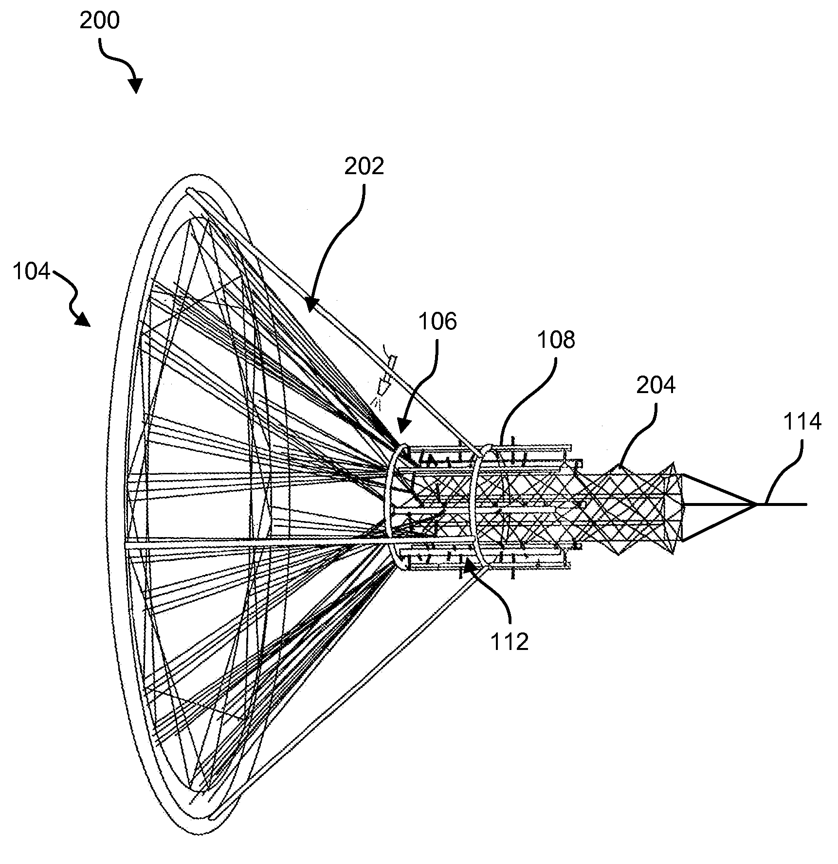
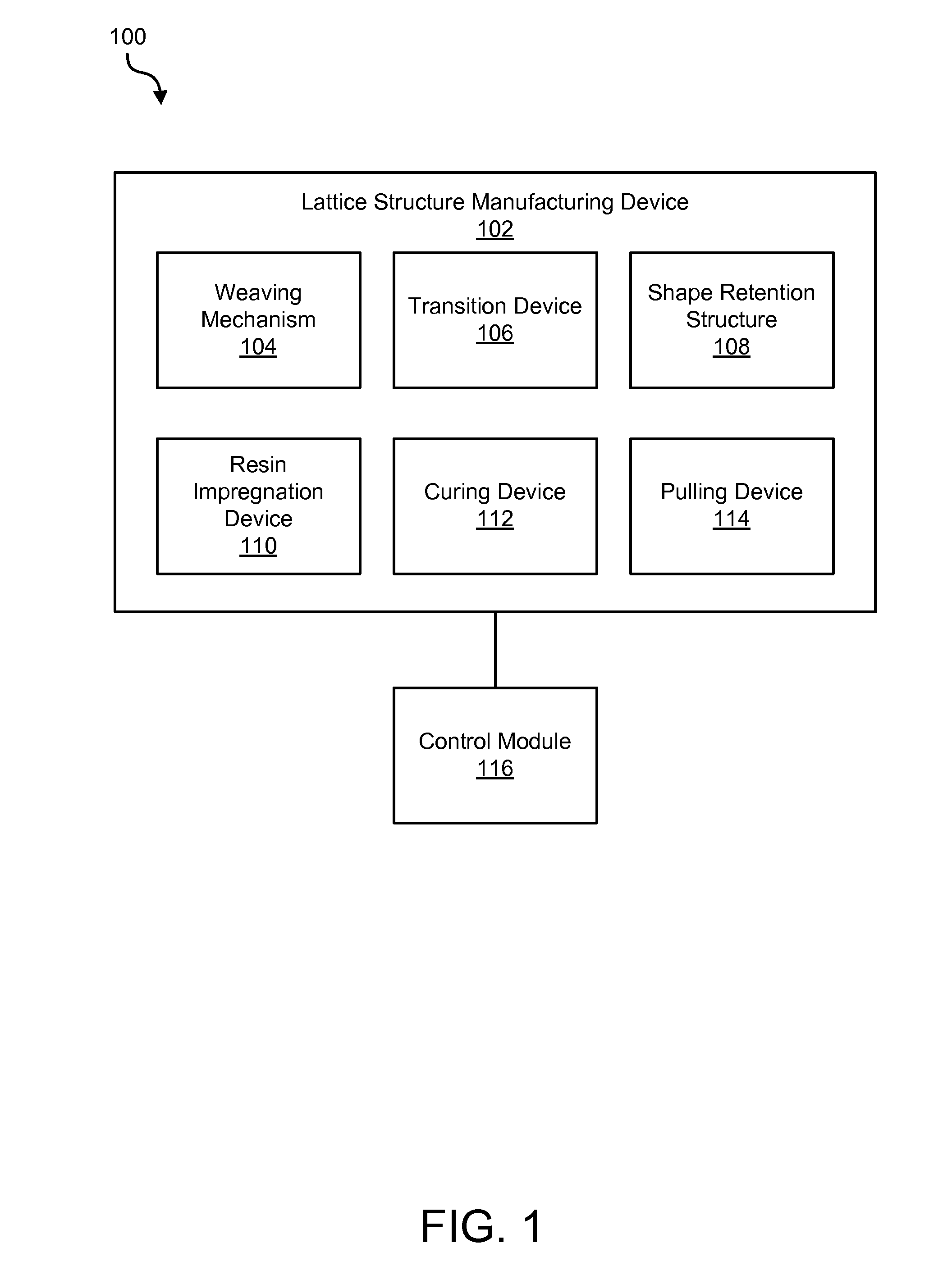
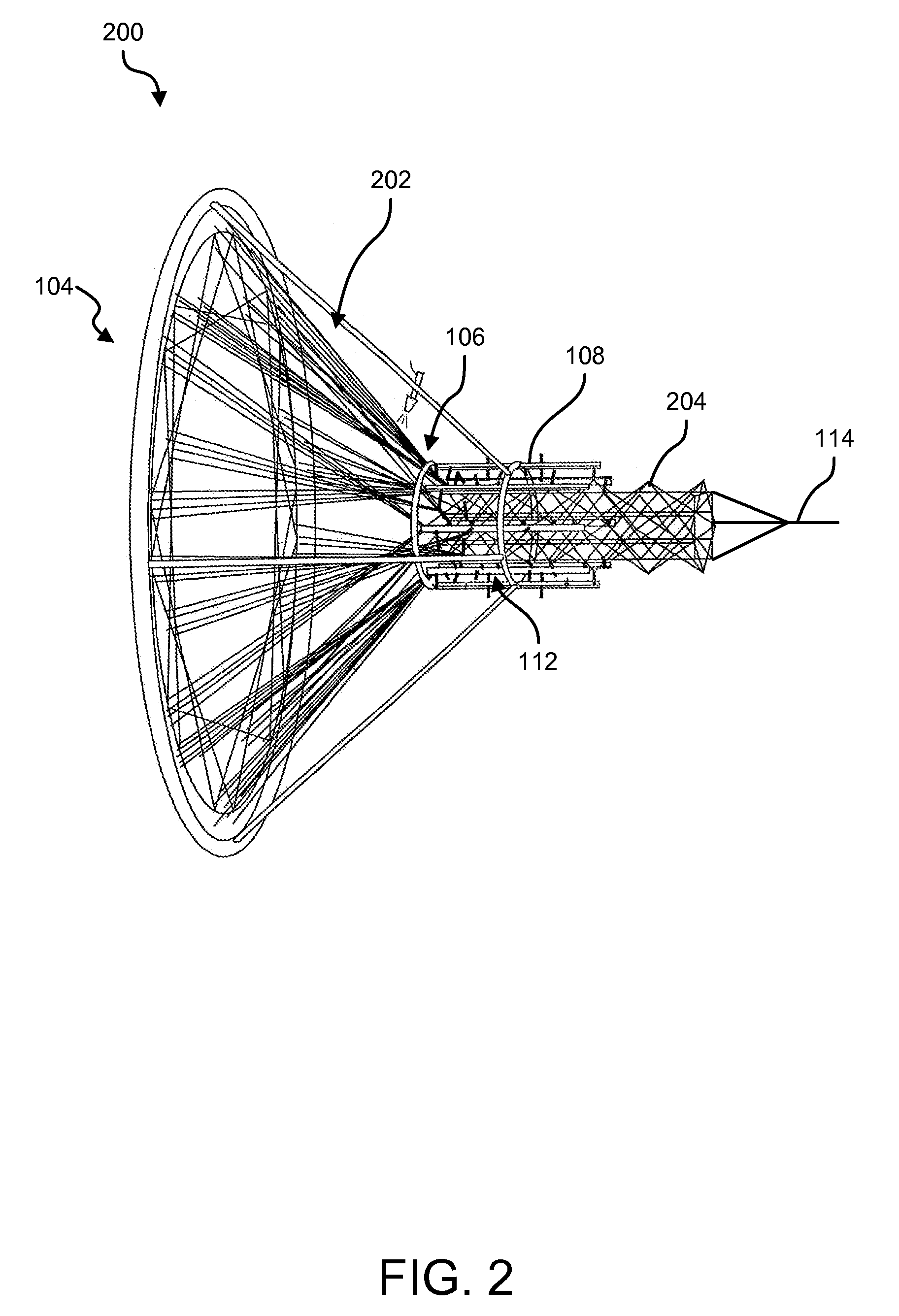
An apparatus, system, and method are disclosed for the manufacture of composite lattice structures comprising a weaving mechanism 104 configured to position fibers in a lattice structure, the weaving mechanism 104 comprising one or more bobbins 304, each one or more bobbin 304 configured to carry fiber and a plurality of horn gears 302 configured to move the one or more bobbins 304 across the face of the weaving mechanism 104 to control the position of the fiber carried by the one or more bobbins 304 in the lattice structure, and a shape retention structure 108 configured to hold the fibers in lattice structure. Beneficially, such an apparatus, system, and method would automate the process of manufacturing composite lattice structures and reduce the costs associated with the existing methods for manufacturing such structures.

Description

CROSS-REFERENCES TO RELATED APPLICATIONS[0001]This application claims the benefit of U.S. Provisional Patent Application No. 60 / 708,558 entitled “Apparatus, System, and Method for Filament Wound Lattice Structure Manufacturing” and filed on Aug. 16, 2005 for David W. Jensen, et al., and PCT Application Number PCT / US2006 / 031903 entitled “Apparatus, System, and Method for Filament Wound Lattice Structure Manufacturing” for David W. Jensen, et al., which is incorporated herein by reference.BACKGROUND OF THE INVENTION[0002]1. Field of the Invention[0003]This invention relates to the manufacture of filamentary composite lattice structures and more particularly relates to the automated manufacture of filamentary composite lattice structures using a weaving component, a shape definition component, and a curing component.[0004]2. Description of the Related Art[0005]The pursuit of structurally efficient structures in the civil, mechanical, and aerospace arenas is an ongoing quest. An efficie...

Claims


Application Information

Patent Timeline
IPC IPC(8): D04C1/00D04C3/00
CPCB29C53/564B29C53/8066B29C70/222D04C3/38D03D37/00D03D47/34D02H1/00
Inventor JENSEN, DAVID W.DAVIS, KEITHGUNNELL, BOYD KIMBERLARSON, GREGORY JAMESBLUNCK, DAVID L.EVANS, TYLERHANSEN, STEVEROGERS, SARITABOYCE, JENNIFERPATE, EVEAYERS III, JAMES T.
Owner BRIGHAM YOUNG UNIV
Learn More