Floating drive-on watercraft docking system

a technology of watercraft and docking system, which is applied in the direction of floating buildings, special-purpose vessels, transportation and packaging, etc., can solve the problem of small amount of propulsion from watercraft needed to load onto the docking system, and achieve the effect of safe and effortless loading and launching of watercra

Inactive Publication Date: 2009-08-06
SUNSTREAM CORP
View PDF22 Cites 16 Cited by
  • Summary
  • Abstract
  • Description
  • Claims
  • Application Information

AI Technical Summary

Benefits of technology

[0007]The disclosed embodiments of the present invention are floating drive-on docking systems for a watercraft that allows for safe and effortless loading and launching of the watercraft, despite the skill level of the watercraft user. The floating drive-on docking system uses a main fl

Problems solved by technology

The floating drive-on docking system uses a main floatation portion where the watercraft rests when loaded and a pivoting entry portion for creating a low loading angle b

Method used


Image

  • Floating drive-on watercraft docking system
  • Floating drive-on watercraft docking system
  • Floating drive-on watercraft docking system

Examples


Embodiment Construction

[0027]This following descriptions illustrate aspects of the invention, and identify preferred embodiments of these aspects. The descriptions are not intended to be exhaustive, but rather to inform and teach the person of skill in the art who will come to appreciate more fully other aspects, equivalents, and possibilities presented by invention, and hence the scope of the invention is set forth in the claims, which alone limit its scope.

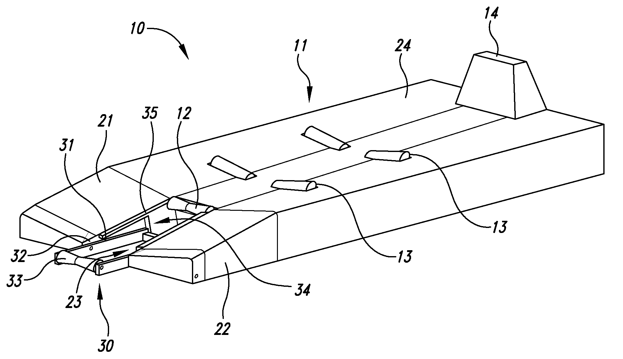
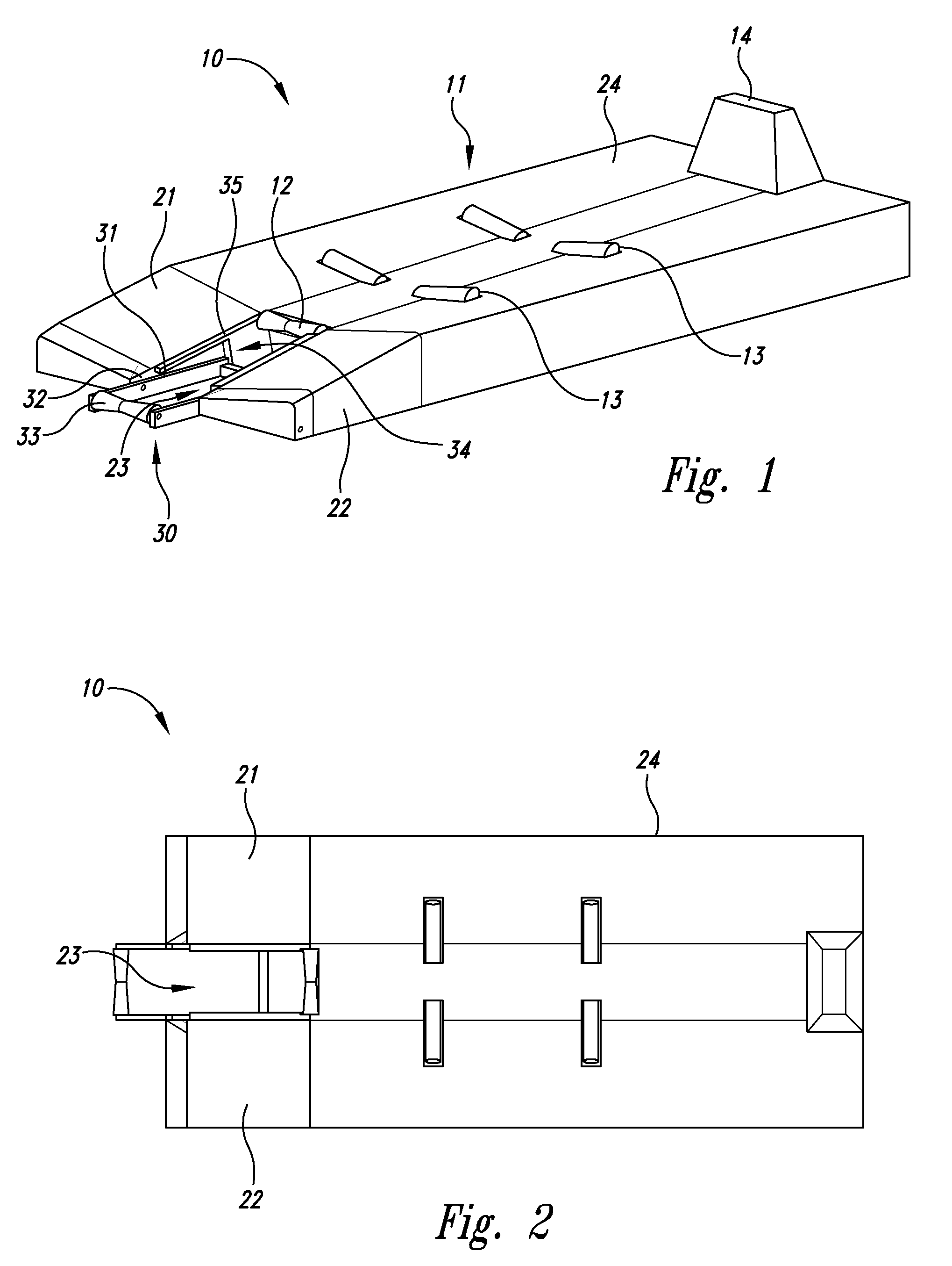
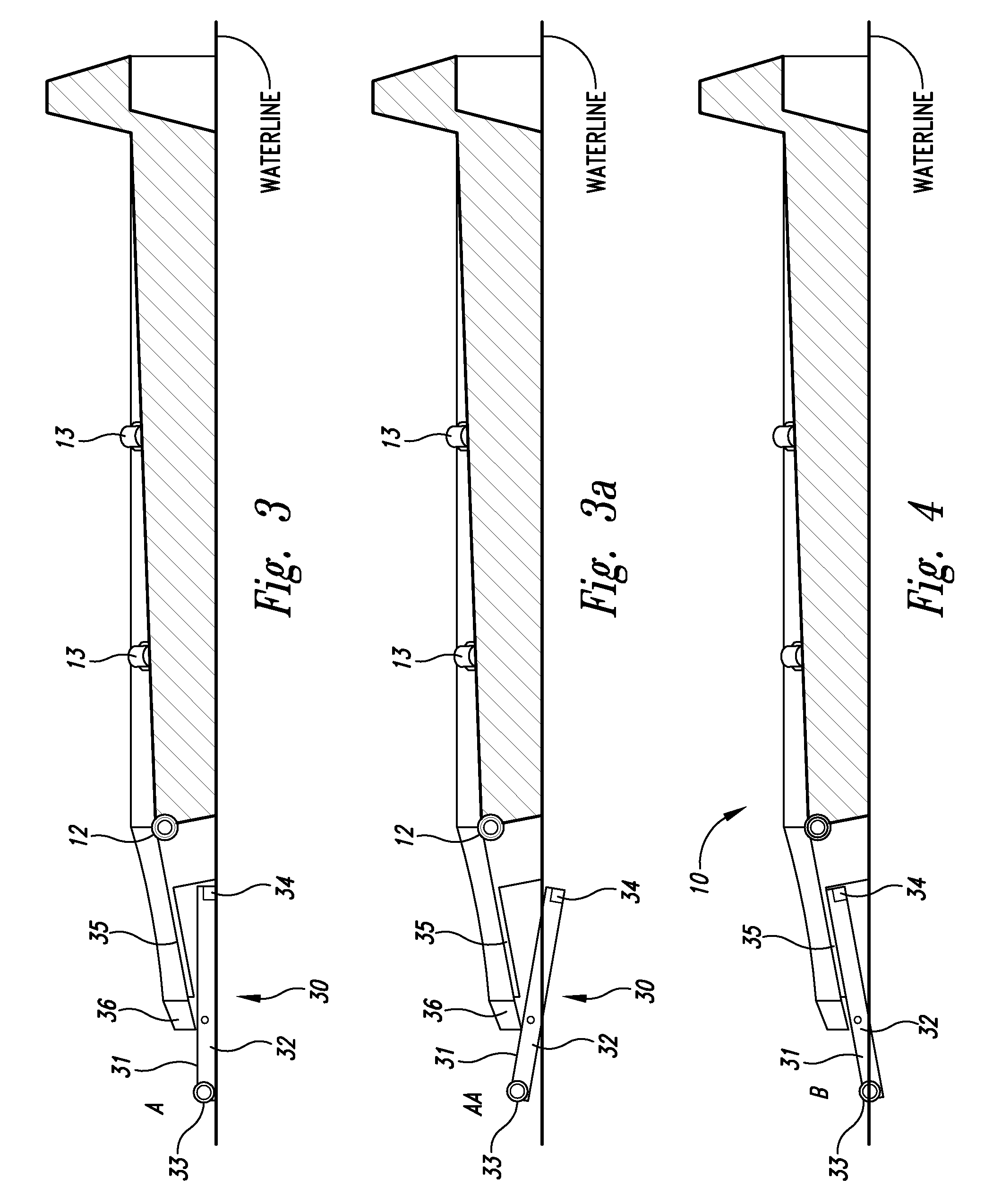
[0028]Several details of the preferred embodiments are set forth in the following description: FIGS. 1 through 14 provide a thorough understanding of such embodiments. One skilled in the art will understand that the present invention may be practiced without several of the details described herein. In the following description of the embodiments, it is understood that a watercraft includes any vehicle that is at least partially waterborne, which includes boats and similar vessels, but may also include amphibious vehicles including various amphibious a...


PUM


Abstract

The floating drive-on docking system for a watercraft uses a main floatation portion where the watercraft rests when loaded and a pivoting entry portion for creating a low loading angle between the watercraft and the floating drive-on docking system, resulting in only a small amount of propulsion from the watercraft being required to load onto the docking system. The pivoting entry portion has entry features, either rollers or raised bumps, that remain above the waterline when not engaged by the watercraft to keep the loading surfaces free from marine growth that can harm the hull of a watercraft. Wide side guides on the pivoting entry portion assist in positioning the craft for loading onto the docking system.

Description

BACKGROUND OF INVENTION[0001]This invention generally relates to a floating drive on docking system for a watercraft and more particularly to a drive-on docking system for a personal watercraft (PWC) with a pivoting entry to allow for easy loading and unloading.[0002]The use of floating drive-on watercraft lifting devices is well known. A number of floating lift designs are currently known that provide this basic function. Most floating drive-on watercraft lifts are made from rotationally molded plastic and are either filled with air or foam for floatation. These lifting devices commonly have a ramped portion for loading and unloading the watercraft, a cradled docked portion for storing the watercraft and some sort of roller system or raised plastic ridges to help in transporting the watercraft from the ramped portion to the cradled portion and visa versa. A common trait among the current floating drive on watercraft lifting devices is a high loading angle between the watercraft and...

Claims


Application Information

Patent Timeline
IPC IPC(8): B63B35/44
CPCB63C3/02
Inventor KLOSTER, BRYCE MORGANHEY, KENNETH E.
Owner SUNSTREAM CORP
Why Eureka
Try Eureka