Antennas Integrated with Dielectric Construction Materials

a technology of dielectric construction materials and antennas, applied in the field of antennas, can solve the problems of obstructing bodies, requiring the use of antennas near, and none acting to address the root cause of problems, and achieve the effect of reducing the number of air interfaces

Active Publication Date: 2009-08-06
PROXENSE
View PDF17 Cites 20 Cited by
  • Summary
  • Abstract
  • Description
  • Claims
  • Application Information

AI Technical Summary

Benefits of technology

[0011]Various drawbacks of the prior art are overcome by making the boundary materials an integral part of the radiation process. For example, in one approach, an (RF) antenna apparatus produces a predetermined radiation pattern, already accounting for the boundary materials. The antenna apparatus includes a construction component suitable for use in building structures, an RF port and one or more radiating element(s) embedded within the construction component. Examples of construction components include components for use in walls, ceiling or floors. The construction component contains a dielectric construction material, for example gypsum board, particle board, plywood, fiberglass, cement board, chipboard wall, floor underlayment materials, Styrofoam, rigid board, insulating foam and ceiling tile materials. The radiating element(s) are embedded within the construction component and radiate directly into the dielectric construction material to produce the predetermined radiation pattern outside the construction component. Since the radiating element(s) are embedded, the relative positions and characteristics of the dielectric construction material are known and can be accounted for in the design of the radiating element(s). Radiating directly into the dielectric construction material reduces the number of air interfaces. The RF port is attached to the construction component and provides an electrical connection from the outside world to the radiating element(s).
[0012]Various implementations may have any of the following features. Examples of radiating element(s) include conducting linear rod(s), conducting flat surface(s) and arrays of conducting elements. Arrays can be planar or non-planar (i.e., three-dimensionally positioned within the construction component), period or non-periodic. The dielectric construction material may be positioned and shaped to produce a “lensing” effect, thus enhancing the directivity of the radiation pattern. The radiation pattern can be one-sided (i.e., directed primarily to one side of the construction component), two-sided (i.e., directed equally to opposite sides of the construction component), or non-directional. If directional, the radiation pattern can have a maximum gain along a direction that is substantially perpendicular to a surface of the construction component (e.g., perpendicular to the surface of a wall). It can also be designed so that the maximum gain is along a direction that is not substantially perpendicular.
[0013]In one particular class of designs, the RF antenna apparatus also includes a conducting sub-reflector embedded within the construction component. The sub-reflector is positioned relative to the radiating element(s) and the dielectric construction material to enhance a directivity of the radiation pattern. For example, the RF antenna apparatus may be designed to produce a radiation pattern primarily to one side of a wall (referred to as the preferred side of the wall). The radiating element(s) may be an array of conducting elements embedded in the wall, with the sub-reflector positioned within the wall but on the opposite side of the radiating element(s) (i.e., towards the non-preferred side of the wall). Thus, the sub-reflector reduces the radiation pattern on the non-preferred side of the wall.
[0015]Many of the features described above can also be applied to the RF antenna assembly. For example, the antenna assembly can be designed to have a one-sided radiation pattern, the dielectric construction material can be used to enhance the directivity of the radiation pattern and / or the antenna assembly can also include a conducting sub-reflector. In one design, the antenna assembly is a conformal structure attachable to the surface of the object by an adhesive compound.

Problems solved by technology

Increased use of Radio Frequencies (RF) and microwaves in consumer and industrial products have created challenges which require the use of antennas near, and in some cases behind or within, obstructing bodies.
Although each is effective in some set of applications, none act to address the root cause of the problem, specifically, the reflection and attenuation of radiation by the non-transparency of the boundaries themselves.
One problem with these approaches is that it typically places dielectric material in close proximity to the antenna, which then alters both the antenna's feed-point impedance and its radiation pattern.
Thus, either each antenna will have to be tuned individually to match its situation, which would require a significant amount of work, or certain antennas will not be tuned to match their individual situations.

Method used


Image

  • Antennas Integrated with Dielectric Construction Materials
  • Antennas Integrated with Dielectric Construction Materials
  • Antennas Integrated with Dielectric Construction Materials

Examples


Embodiment Construction

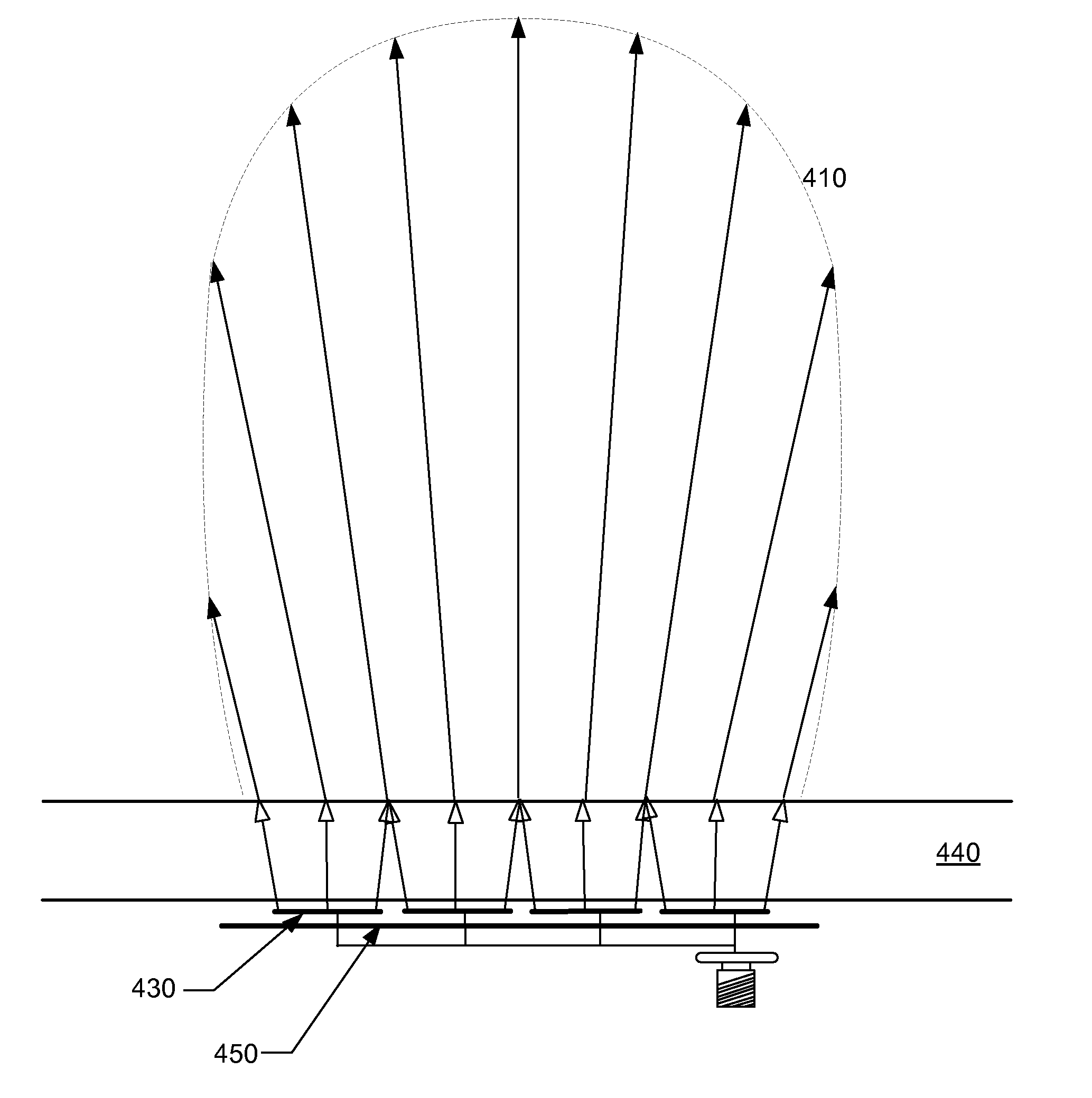
[0023]FIG. 2 shows a cross-section of an example unidirectional antenna apparatus 200 according to the invention. In this example, the radiating structure resides wholly within the dielectric construction material 240 of a construction component 249. The radiating structure in this example includes four radiating patch elements 230 (which could be linear, circular, serpentine or other), dielectric backing 242 and sub-reflector 250. The dielectric backing 242, which is a portion of the dielectric construction material 240, is designed to provide both a substance to mechanically support the radiating elements 230 and to provide an increase in the dielectric constant of the material 242 behind the radiating elements 230 relative to air. This latter effect acts to reduce the spacing required between the radiating elements 230 and the sub-reflector 250, such reduction in overall volume being a desirable quality. An RF port 260 is also attached to the construction component 249 and provid...


PUM


Abstract

Antenna radiating elements are combined with dielectric construction materials, with the radiating elements designed to produce a certain radiation pattern taking into account the construction materials.

Description

CROSS-REFERENCE TO RELATED APPLICATIONS[0001]The present application claims the benefit of priority under 35 U.S.C. § 119(e) of U.S. Provisional Application No. 60 / 985,038 entitled “Integrated Dielectric-Lensed Location-Tracking Antennas Fabricated Within Common Construction Materials” filed on Nov. 2, 2007, the entire contents of which are incorporated by reference herein.BACKGROUND[0002]1. Field of Art[0003]The invention generally relates to antennas, including for example the combination of RF radiating elements with dielectric construction materials.[0004]2. Description of the Related Art[0005]Traditionally, antennas were positioned, and aimed, to avoid obstructions in order to both minimize losses and preserve the antenna's theoretical, free-space radiation pattern. Increased use of Radio Frequencies (RF) and microwaves in consumer and industrial products have created challenges which require the use of antennas near, and in some cases behind or within, obstructing bodies. Exam...

Claims


Application Information

Patent Timeline
Patent Type & Authority Applications(United States)
IPC IPC(8): H01Q1/24
CPCH01Q1/42H01Q1/44H01Q1/40H01Q21/06H01Q19/10
Inventor HIRT, FRED S.
Owner PROXENSE
Why Eureka
Try Eureka