

Liquid crystal display device controlling method, liquid crystal display device, and electronic apparatus
- Summary
- Abstract
- Description
- Claims
- Application Information
AI Technical Summary
Benefits of technology
Problems solved by technology
Method used
Image

Examples
Embodiment Construction
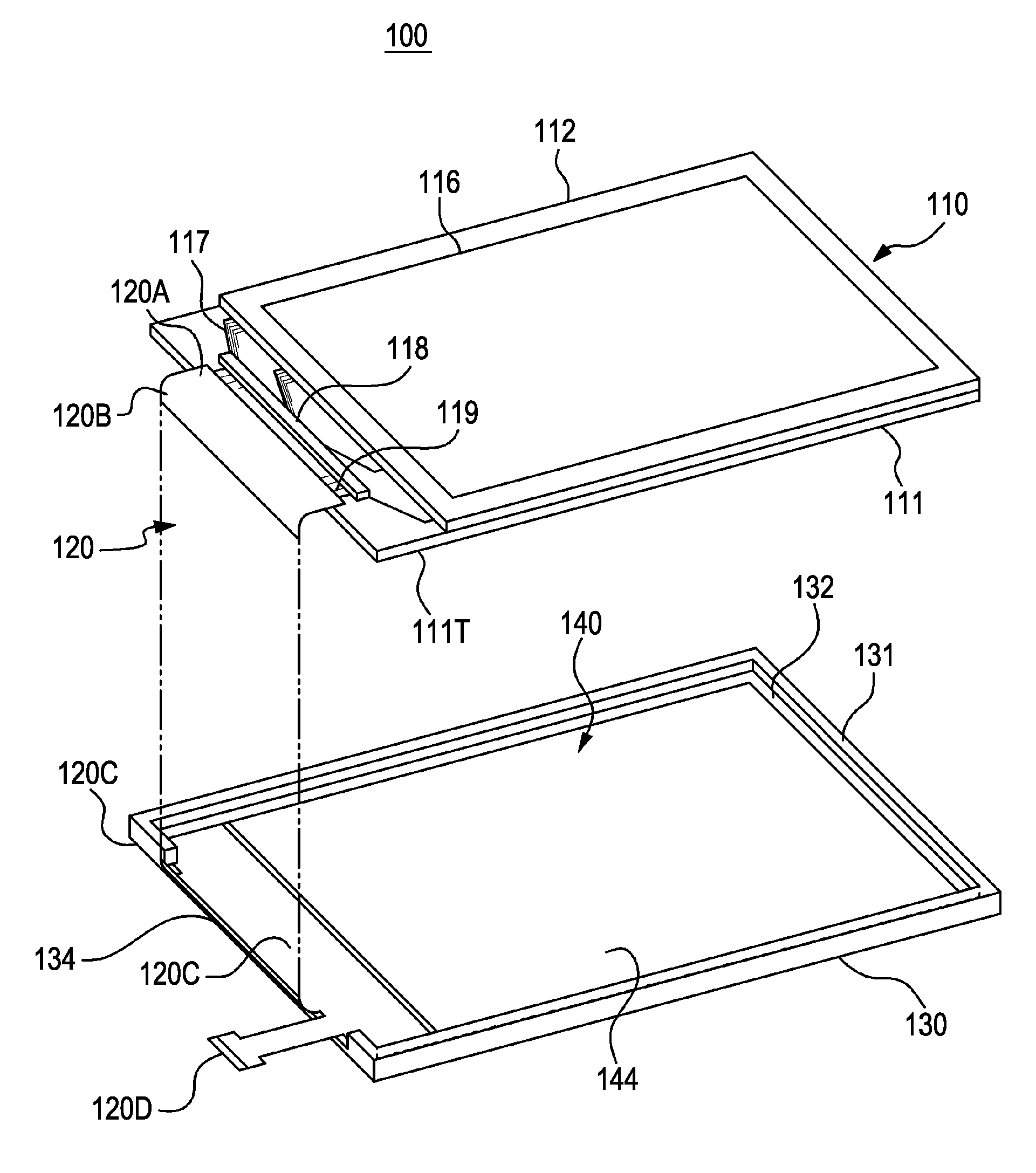
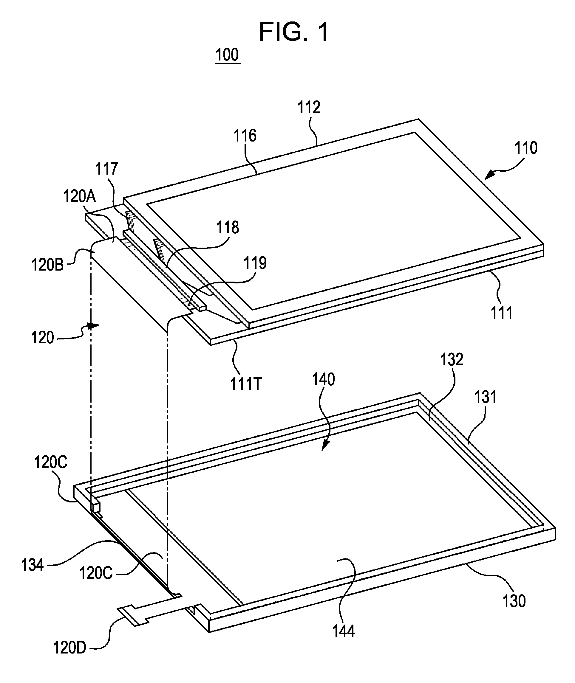
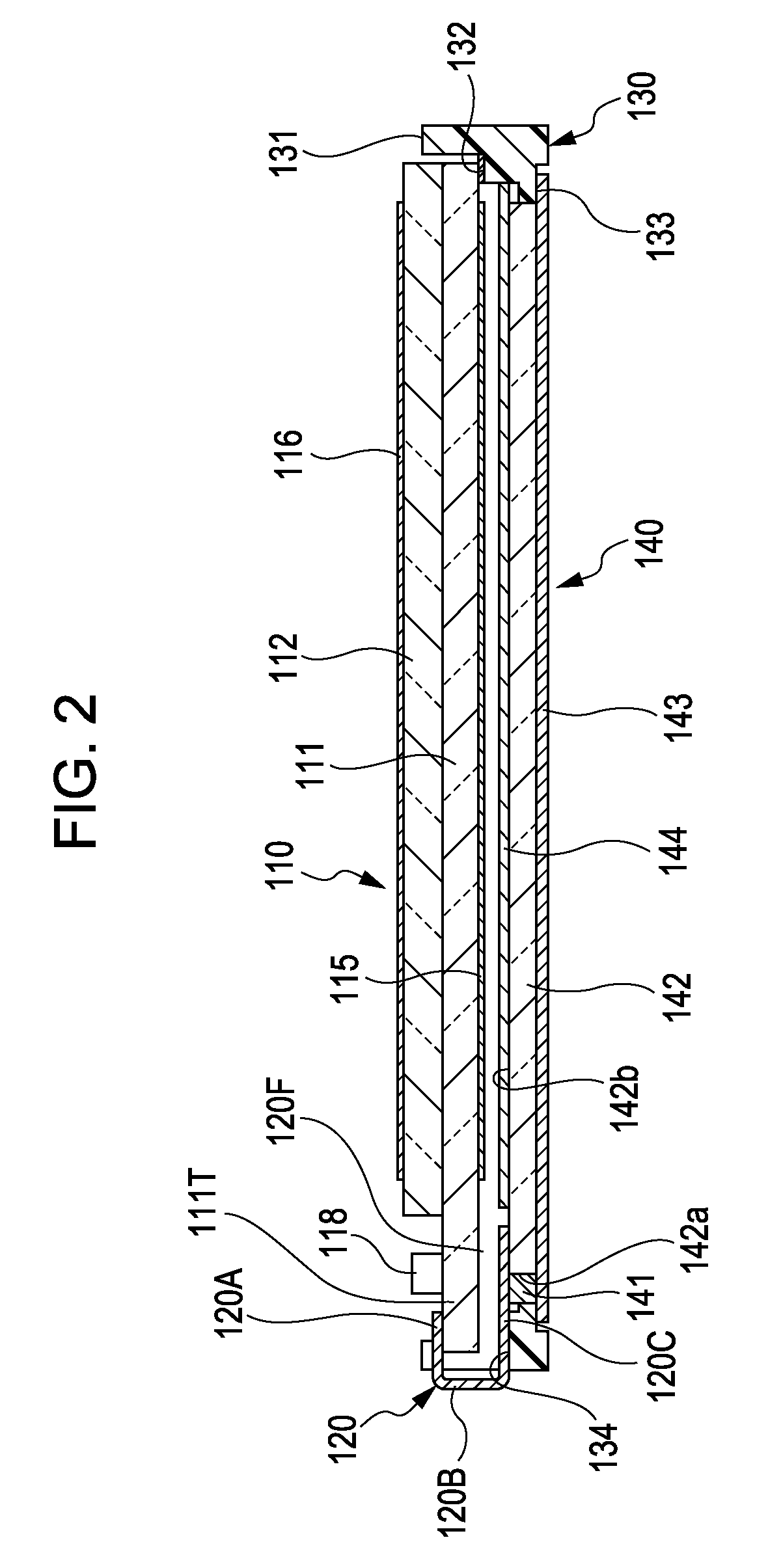
[0046]An embodiment of the invention will be described in detail with reference to the accompanying drawings. FIG. 1 is an exploded perspective view illustrating a liquid crystal display device 100 forming a display unit of a display device according to the embodiment. FIG. 2 is a longitudinal sectional view illustrating the liquid crystal display device 100. In this embodiment, the liquid crystal display device 100 includes a liquid crystal panel 110. The liquid crystal panel 110 includes a transparent substrate 111 formed of glass or the like and a substrate 112 which are adhered by a seal member (not shown) with a liquid crystal (TN liquid crystal) layer (not shown) interposed therebetween. Polarizing plates 115 and 116 are adhered on the outward appearances of the substrates 111 and 112, respectively.
[0047]A substrate extension portion 111T extending outward more than the appearance of the substrate 112 is provided in the substrate 111. In the substrate extension portion 111T, a...
PUM
 Abstract
Description
Claims
Application Information