Three-dimensional image reproducing apparatus

a three-dimensional image and reproducing technology, applied in the field of three-dimensional image reproducing apparatus, can solve the problems of large-scale apparatus and inconvenience, loss of stereoscopic effect, and optical configuration required to perform conventional stereographs with the naked eye, so as to prevent crosstalk between adjacent lenses or adjacent hologram optical elements, stable stereoscopic image, and avoid distortion or shift of images

Inactive Publication Date: 2009-08-06
PANASONIC CORP
View PDF8 Cites 24 Cited by
  • Summary
  • Abstract
  • Description
  • Claims
  • Application Information

AI Technical Summary

Benefits of technology

[0018]According to the present invention, occurrence of crosstalk between adjacent lenses or adjacent hologram optical elements can be prevented. Thus, an image that should not originally be displayed is not displayed on the adjacent lens or the adjacent hologram optical element. As a consequence, di...

Problems solved by technology

Hence, the display device in principle involves a problem of loss of a stereoscopic effect when the positions of the right and left eyes of the observer deviate from the horizontal direction.
However, the method entails a large-scale apparatus and inconvenience of equipping an observer with a marker to sense the positions of eyes and the position of a face.
However, the optical configuration required to perform conventional stereograph with na...

Method used


Image

  • Three-dimensional image reproducing apparatus
  • Three-dimensional image reproducing apparatus
  • Three-dimensional image reproducing apparatus

Examples


first embodiment

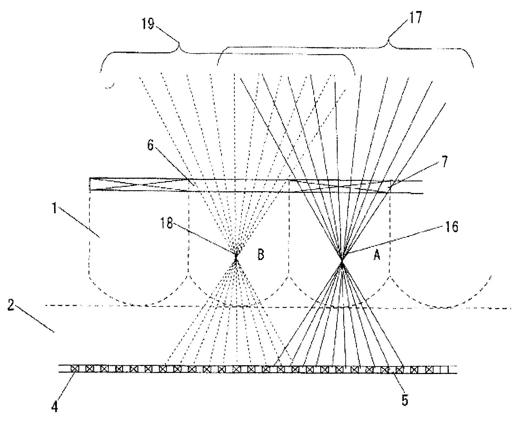
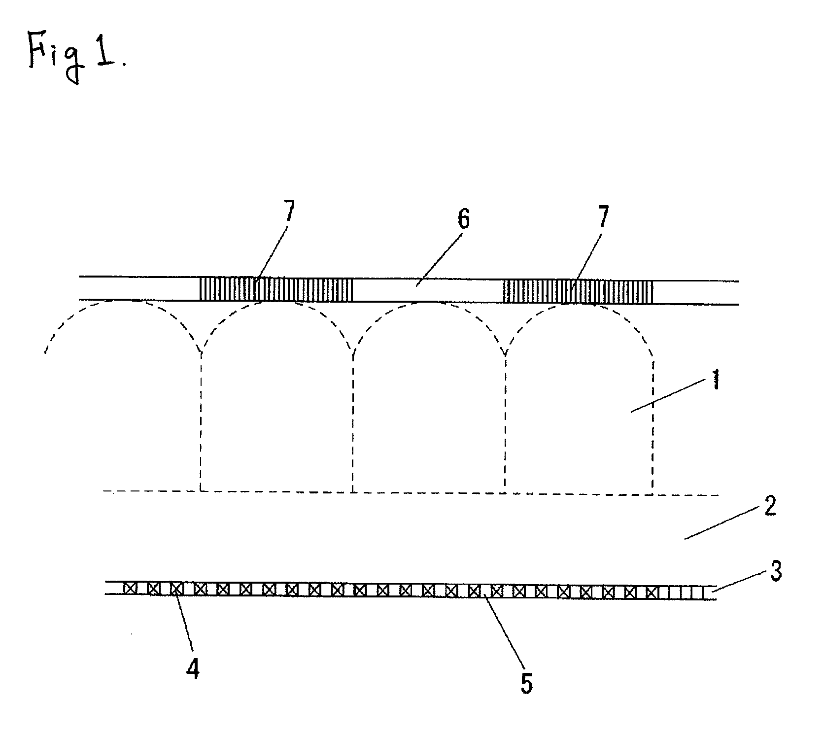
[0032]FIG. 1 is a view showing a configuration for preventing crosstalk by a difference in polarizing characteristic; namely, the principal part of a three-dimensional image reproducing apparatus of a first embodiment of the present invention. In the first embodiment, a configuration for preventing crosstalk between adjacent lenses is described.

[0033]Specifically, the first embodiment shows a configuration for preventing a crosstalk between adjacent lenses. In the configuration, a plurality of images each of which has a different parallax information provided on a focus plane of the array of lenses so that a polarized characters of a ray from each of the images are different from each other in order that the ray passes through corresponding one of the optical elements, and a polarizing plate provided on an emitting side of the optical elements and having a polarized character which is different on the adjacent optical elements and same on the next adjacent optical elements.

[0034]In ...

second embodiment

[0060]FIG. 5 is a view showing a configuration that prevents crosstalk by use of two plane-convex lenses; namely, the principal part of a three-dimensional image reproducing apparatus of a second embodiment of the present invention. The second embodiment shows an example configuration for preventing crosstalk among lenses.

[0061]As shown in FIG. 5, two plane-convex lenses 21 and 22 are configured such that convex sides are oriented to the outside. Thus, a view angle is broadened by the combination, and hence occurrence of crosstalk can be prevented.

[0062]An acrylic resin, polyethylene terephthalate, an episulphide resin, and the like, can be used as a material for the two plane-convex lenses 21 and 22. However, the following difference exists between the plane-convex lenses.

[0063]The curvature radius of the convex lens of one of the plane-convex lens 21 which is facing to the two dimensional image 20 including parallax information is smaller than that of the other plane-convex lens 2...

third embodiment

[0067]FIG. 6 is a view showing a configuration that prevents occurrence of crosstalk by use of an integrated waveguide; namely, the principal unit of a three-dimensional image reproducing apparatus of a third embodiment of the present invention. The third embodiment shows an example configuration for preventing occurrence of crosstalk between lenses.

[0068]As shown in FIG. 6, an integrated waveguide 23 is positioned in close contact with the two-dimensional image 3 including parallax information so as to direct the two dimensional image 3 to the principal point of the lens 1. Accordingly, as the adjacent lenses 1 are optically separated, crosstalk is prevented.

[0069]The integrated waveguide 23 is made of a visual field limitation film or glass fiber, thereby making it possible to more efficiently, optically separate adjacent lenses.

[0070]According to the third embodiment, occurrence of crosstalk between lenses can be prevented. Hence, an image that should not be originally displayed ...


PUM


Abstract

The invention provides a three-dimensional image reproducing apparatus that enables stable provision of a three-dimensional image display by preventing occurrence of crosstalk between adjacent lenses or adjacent hologram optical elements and eliminating shift of a three-dimensional image. The three-dimensional image reproduce apparatus of the invention includes an array of adjacent optical elements, which is an array of lenticular lens, an fly-eye lens array and an array of hologram optical elements, and a cross-talk prevent part preventing cross-talk between the adjacent optical elements and having an image source providing a plurality of images each of which has a different parallax information.

Description

BACKGROUND OF THE INVENTION[0001]The present invention relates to a three-dimensional image reproducing apparatus that reproduces a stereographic image by use of a lenticular lens array, a fly-eye lens array, or a hologram optical element.[0002]A parallel-vision random dot stereogram method under which a right-side stereographic image including binocular parallax is viewed with a right eye and which a left-side stereographic image including binocular parallax is viewed with a left eye, a stereoscope method under which a view is acquired by use of eyeglasses with a liquid-crystal shutter or by using one lens for a right eye and another lens for a left eye, and an anaglyph method under which a red binocular parallax picture and a blue binocular parallax picture, both of which differ from each other in only color, are viewed by use of red-and-blue eyeglasses, and other methods, have been known as methods for displaying three-dimensional image information since old times. However, when ...

Claims


Application Information

Patent Timeline
IPC IPC(8): G02B27/22G02B5/32G02B30/25G02B30/27
CPCG02B5/32G02B27/2214H04N13/0497H04N13/0406H04N13/0409H04N13/0404H04N13/305H04N13/31H04N13/307H04N13/398G02B30/27
Inventor KUBARA, TAKASHI
Owner PANASONIC CORP
Why Eureka
Try Eureka