Apparatus and related methods for turbine cooling

a technology of apparatus and turbine, applied in mechanical apparatus, machines/engines, liquid fuel engines, etc., can solve the problems of reducing the efficiency of the engine, excessive compressor bleed on other operating conditions, loss of both useful power output and efficiency, etc., to improve the efficiency of the turbomachine, less chargeable air, and increase the effect of mass flow

Inactive Publication Date: 2009-08-06
GENERAL ELECTRIC CO
View PDF9 Cites 66 Cited by
  • Summary
  • Abstract
  • Description
  • Claims
  • Application Information

AI Technical Summary

Benefits of technology

[0010]Described herein is an apparatus and a method for regulating the fluid flow in turbomachinery by selectively boosting the pressure of the fluid flow extracted from an extraction stage. A first fluid flow is established at a compressor of the turbomachinery and directed to an external component of the turbomachinery for selective boosting of the pressure of the fluid flow. The resulting second fluid flow is directed to an interior component of the turbomachinery for cooling. The method eliminates the need for raising the pressure much above the supply point pressure, as dictated by the available compressor extraction ports, as done in conventional design, thus enhancing the efficiency of the turbomachinery being cooled, for example, gas turbines. The resulting decrease in the discharge temperature of the cooling air yields a decrease in total mass extracted from the compressor, thus producing less chargeable air being added downstream of the combustion chamber of the turbomachinery. The increased mass flow to the combustor provides more power output by burning more fuel in the gas turbine.

Problems solved by technology

Any air compressed in the compressor and not used in generating combustion gases reduces the efficiency of the engine.
However, sizing the system for meeting the design requirements (for example, minimum flow, backpressure margin, source to sink pressure ratio) at worst operating conditions (i.e., operating load, ambient temperature) leads to excessive compressor bleed on other operating conditions.
This leads to loss in both useful power output and efficiency.
However, the static orifice does not adjust to day variations in the ambient temperature.
As the variation in the ambient temperature causes variation in the air pressure, this design leads to excess cooling flow extraction and concomitant performance penalty.
However, this does not eliminate the throttling requirement.
However, this method requires the external compressor to supply high pressure ratios and hence must be designed accordingly.
In addition, the volume flow rates involved are high, thus increasing the external compressor size, weight and, consequently, the cost.

Method used


Image

  • Apparatus and related methods for turbine cooling
  • Apparatus and related methods for turbine cooling
  • Apparatus and related methods for turbine cooling

Examples


Embodiment Construction

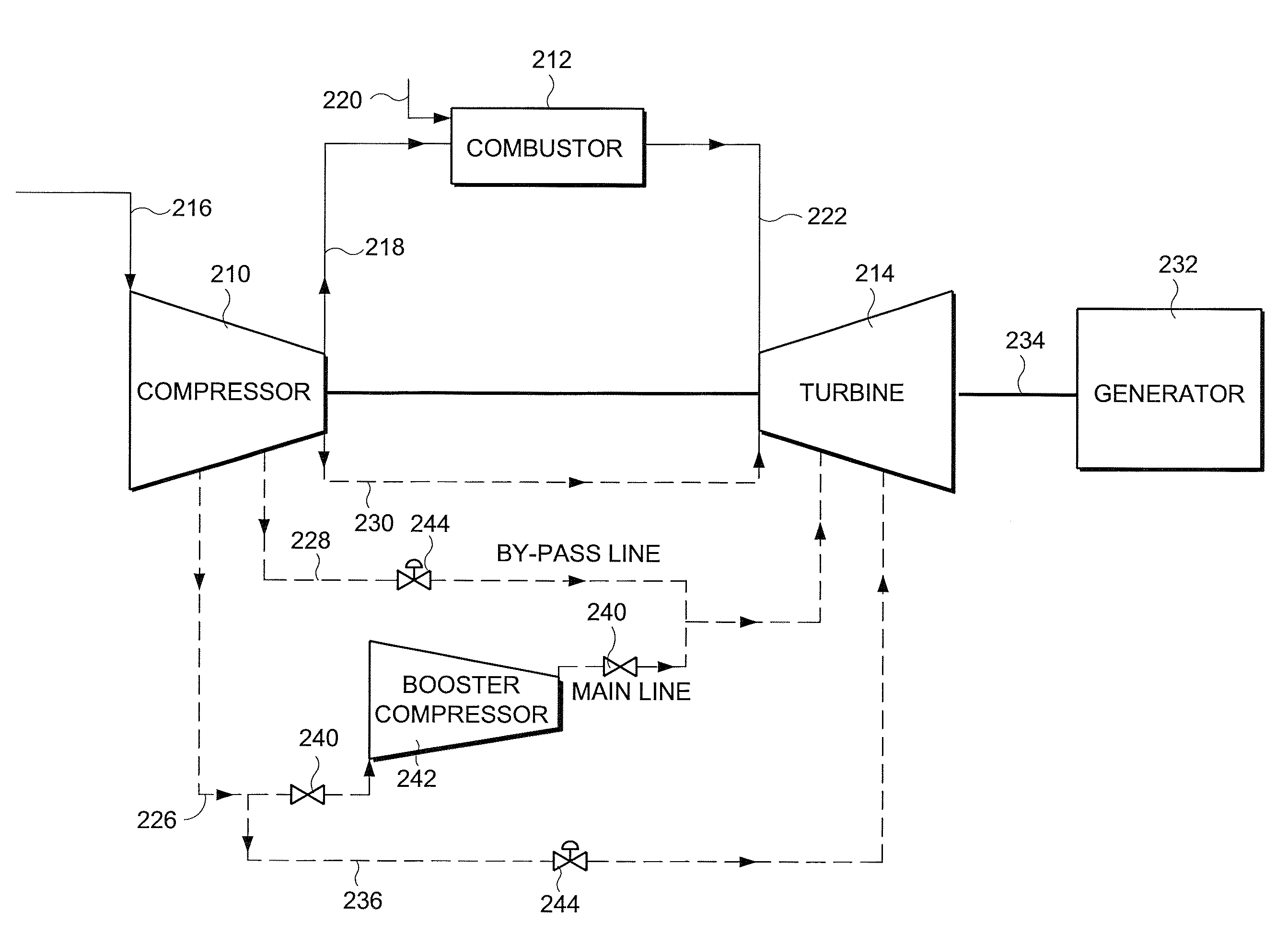
[0016]FIG. 3 shows an exemplary illustrative embodiment for controlling the characteristics of fluid flow in turbomachinery using selective boosting. Again, for the sake of convenience, reference numerals similar to those used in FIG. 1 are used for corresponding components, but with the prefix “2” added. The term selective boosting signifies raising the pressure of air, at least in part, extracted from an extraction stage of a compressor of the turbomachinery to a desired value, and then using this air for cooling and / or sealing of the gas turbine components of the turbomachinery, instead of directly using compressor air of high pressure as the cooling air.

[0017]In one exemplary illustrative embodiment, air 226 is extracted from a compressor stage having air of relatively lower pressure (for example, 9th stage), which after passing through isolation valve 240 reaches external booster compressor 242. The external compressor raises the pressure of the input air to a required value an...


PUM


Abstract

An apparatus and a method for cooling and/or sealing a gas turbine by selectively boosting the pressure of air extracted at a lower extraction stage is provided. The pressure of the extracted air is boosted by an external compressor before it becomes available for cooling and/or sealing the turbine components. A bypass line includes a higher extraction stage providing air for cooling the turbine.

Description

BACKGROUND OF THE INVENTION[0001]Gas turbines (“GT”) generally use air bled from one or more stages / ports of the main GT compressor to provide cooling and / or sealing of the components in the path of hot gasses inside the GT. Air is extracted from the compressor and externally routed to the locations that require cooling in the turbine section. Any air compressed in the compressor and not used in generating combustion gases reduces the efficiency of the engine. Therefore, it is desirable to reduce the amount of cooling air bled from the compressor.[0002]This air must have sufficiently higher pressure compared to the pressure of the hot combustion gas inside the GT (back pressure margin), to prevent inadvertent hot gas ingestion into the cooling system. The pressure required by the turbine components determines the stage where the air is extracted from the compressor. To ensure sufficient delivery pressure, it is desirable to select the extraction stage / port with higher pressures. Loc...

Claims


Application Information

Patent Timeline
Patent Type & Authority Applications(United States)
IPC IPC(8): F01D5/08
CPCF01D11/04F01D11/10F02C7/18F02C6/08F01D25/12
Inventor SENGAR, AJIT SINGHSARAVANAN, NATTAMAI VENKATARAMANSUBRAMANYA, NAGARAJ SATHYA
Owner GENERAL ELECTRIC CO
Why Eureka
Try Eureka