
Multi-gated, high-mobility, density improved devices

a technology of density improvement and multi-gated devices, which is applied in the direction of semiconductors, semiconductor devices, electrical equipment, etc., can solve the problems of unique density and scalability problems of high-mobility semiconductor fins of cmos devices

Inactive Publication Date: 2009-08-06
GLOBALFOUNDRIES INC
View PDF6 Cites 22 Cited by
  • Summary
  • Abstract
  • Description
  • Claims
  • Application Information

AI Technical Summary

Benefits of technology

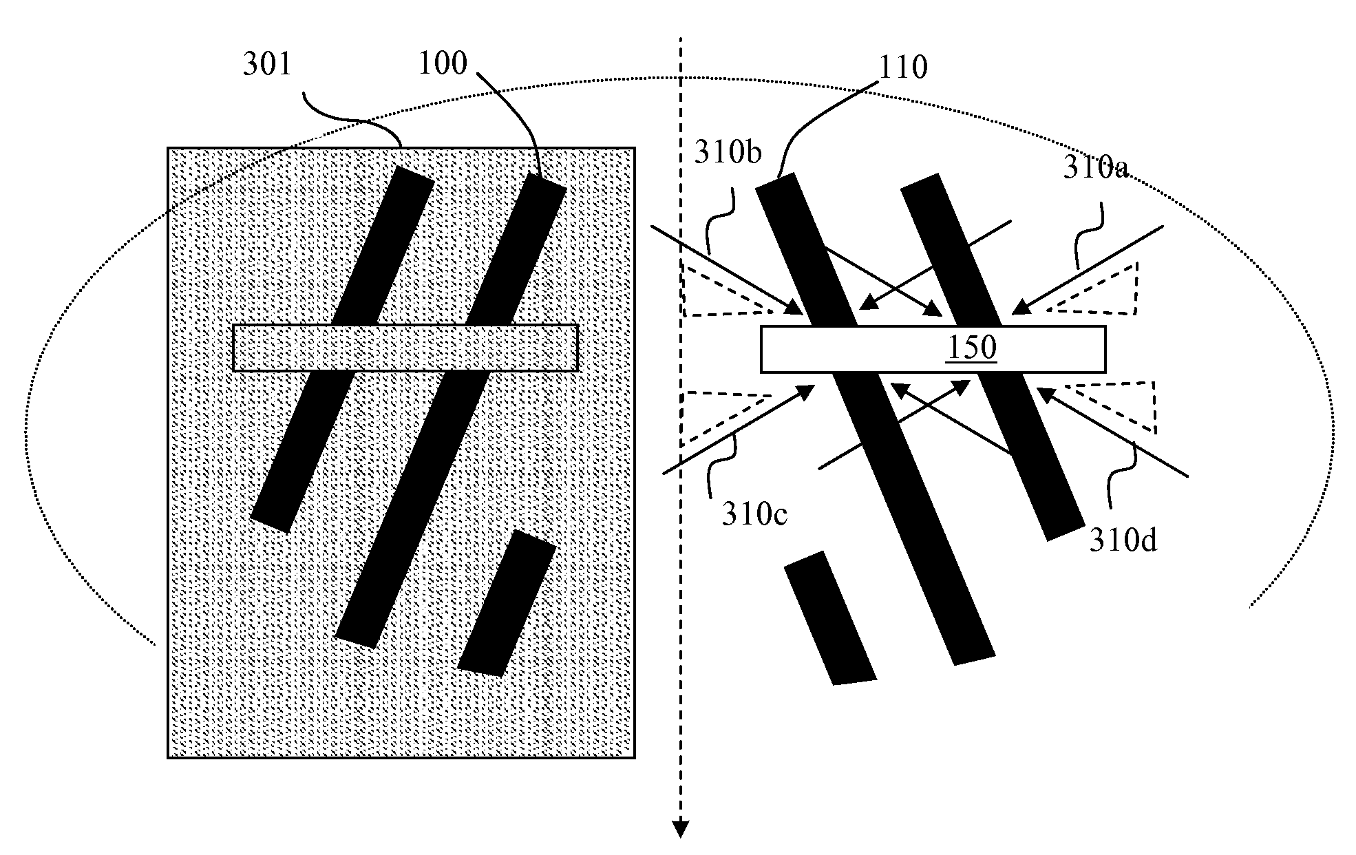
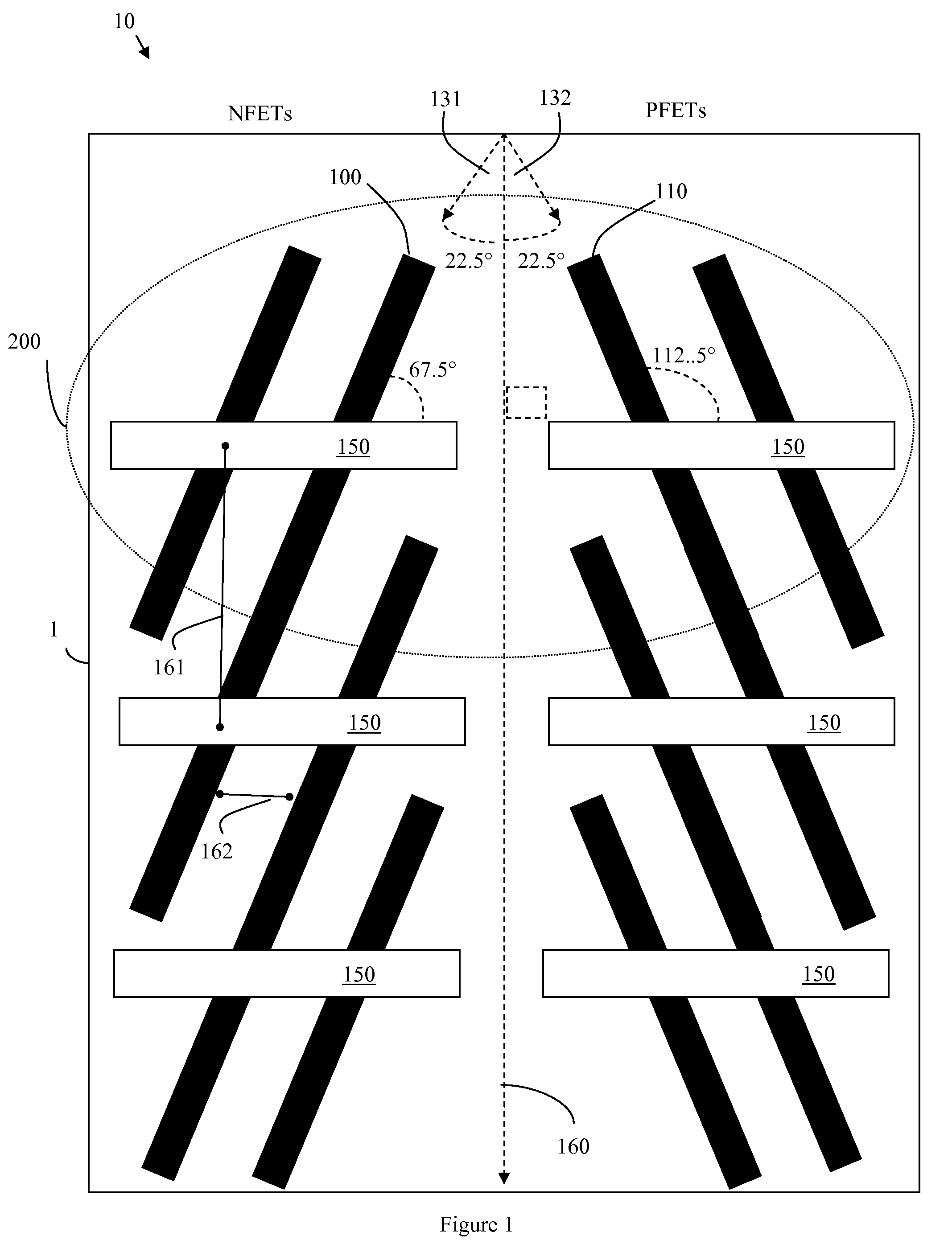
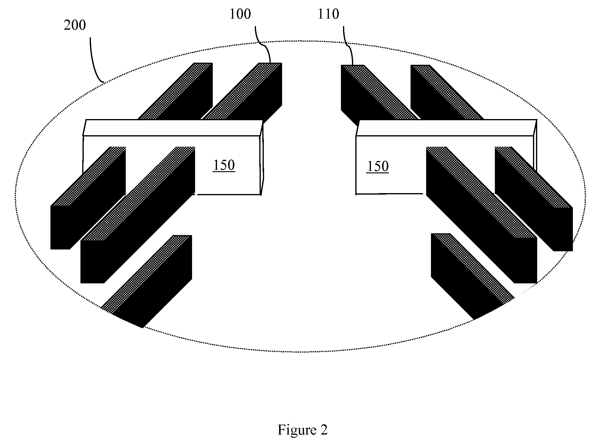
[0006]Disclosed herein are embodiments of an improved method of forming p-type and n-type MUGFETs with high-mobility crystalline planes in high-density, chevron-patterned, CMOS devices. Specifically, semiconductor fins are formed in a chevron layout oriented along a centerline of a wafer. Gates are formed adjacent to the semiconductor fins such that they are approximately perpendicular to the centerline. Then, masked implant sequences are performed, during which halo and / or source / drain dopants are implanted into the opposing sidewalls of the semiconductor fins on one side of the chevron layout and then into the opposing sidewalls of the semiconductor fins on the opposite side of the chevron layout. The implant direction used during these implant sequences is substantially orthogonal to the gates in order to avoid mask shadowing, which can obstruct dopant implantation when separation between the semiconductor fins in the chevron layout is scaled (i.e., when device density is increased).
[0009]The process is repeated for the first semiconductor body. Specifically, the first mask is removed from the first semiconductor body and a second mask is formed covering the second semiconductor body. Next, a second implant sequence is performed so as to implant additional dopants (e.g., halos and / or source / drain extension dopants for a second type FET, such as an NFET) into the opposing sidewalls of the first semiconductor body. As with the first implant sequence, the second implant sequence comprises directing the additional dopants into the first semiconductor body at a first angle relative to the gates and, then, directing the additional dopants into the first semiconductor body at a second angle relative to the gates. The implant angles can be the same for the second implant sequence as they are for the first implant sequence. That is, the first angle and the second angle of the second implant sequence can be pre-selected to ensure that implantation of the additional dopants into the opposing sidewalls of the first semiconductor body is not obstructed by the second mask. For example, the first angle can be an approximately 90° angle relative to the gates and the second angle can be an approximately 270° angle relative to the gates. Implanting the additional dopants into the sidewalls of the first semiconductor body from a direction that is substantially orthogonal to the gates prevents shadowing by the second mask over the first semiconductor body.

Problems solved by technology

However, due to the different fin angles (i.e., due to the chevron pattern), CMOS devices with such high mobility semiconductor fins are subject to unique density and scalability issues as compared to conventional CMOS devices.

Method used


Image

  • Multi-gated, high-mobility, density improved devices
  • Multi-gated, high-mobility, density improved devices
  • Multi-gated, high-mobility, density improved devices

Examples


Embodiment Construction

[0019]The embodiments of the invention and the various features and advantageous details thereof are explained more fully with reference to the non-limiting embodiments that are illustrated in the accompanying drawings and detailed in the following description. It should be noted that the features illustrated in the drawings are not necessarily drawn to scale. Descriptions of well-known components and processing techniques are omitted so as to not unnecessarily obscure the embodiments of the invention. The examples used herein are intended merely to facilitate an understanding of ways in which the embodiments of the invention may be practiced and to further enable those of skill in the art to practice the embodiments of the invention. Accordingly, the examples should not be construed as limiting the scope of the embodiments of the invention.

[0020]As mentioned above, integrated circuit design decisions are often driven by device scalability and manufacturing efficiency. For example, ...


PUM


Abstract

Disclosed herein are embodiments of an improved method of forming p-type and n-type MUGFETs with high mobility crystalline planes in high-density, chevron-patterned, CMOS devices. Specifically, semiconductor fins are formed in a chevron layout oriented along the centerline of a wafer. Gates are formed adjacent to the semiconductor fins such that they are approximately perpendicular to the centerline. Then, masked implant sequences are performed, during which halo and / or source / drain dopants are implanted into the sidewalls of the semiconductor fins on one side of the chevron layout and then into the sidewalls of the semiconductor fins on the opposite side of the chevron layout. The implant direction used during these implant sequences is substantially orthogonal to the gates in order to avoid mask shadowing, which can obstruct dopant implantation when separation between the semiconductor fins in the chevron layout is scaled (i.e., when device density is increased).

Description

BACKGROUND[0001]1. Field of the Invention[0002]The embodiments of the invention generally relate to complementary metal oxide semiconductor (CMOS) devices and, more particularly, to an improved method for forming p-type and n-type, multi-gated, non-planar, field effect transistors (MUGFETs) with high mobility crystalline semiconductor fins in high-density, chevron-patterned, CMOS devices.[0003]2. Description of the Related Art[0004]Integrated circuit design decisions are often driven by device scalability and manufacturing efficiency. For example, as the size of planar field effect transistors (planar FETs) is reduced, generally so is the drive current. In response, MUGFETs, such as fin-type FETs (FINFETs) or trigate FETs, were developed to provide scaled devices with faster drive currents and reduced short channel effects.[0005]Integrated circuit design decisions are also driven by a desire for improved performance, such as a desire to reduce device delay. For example, in both NFET...

Claims


Application Information

Patent Timeline
IPC IPC(8): H01L21/336
CPCH01L21/26513H01L21/26586H01L29/785H01L29/66803H01L21/845H01L21/26546
Inventor ANDERSON, BRENT A.BRYANT, ANDRESNOWAK, EDWARD J.
Owner GLOBALFOUNDRIES INC
Learn More