Damped Axle Shaft

a technology of axle shaft and damping ring, which is applied in the direction of mechanical equipment, rotary machine parts, organic active ingredients, etc., can solve the problems of relative displacement and energy dissipation by elastic deformation of the damping ring

Inactive Publication Date: 2009-08-06
GM GLOBAL TECH OPERATIONS LLC
View PDF18 Cites 20 Cited by
  • Summary
  • Abstract
  • Description
  • Claims
  • Application Information

AI Technical Summary

Benefits of technology

[0010]The present invention is an axle shaft which is inherently damped very near the source of the oscillation, via inner and outer axle components with at least one damping ring that couples between them, wherein the inner component has a torsional stiffness different from that of the outer component. Under torsional load, both the inner and outer compon...

Problems solved by technology

Under torsional load, both the inner and outer components transmit the torsional load, wherein the inner component twists more than the outer component, resulting in relative displacement therebetween.
The damping ring, which is a high damping e...

Method used


Image

  • Damped Axle Shaft
  • Damped Axle Shaft
  • Damped Axle Shaft

Examples


Embodiment Construction

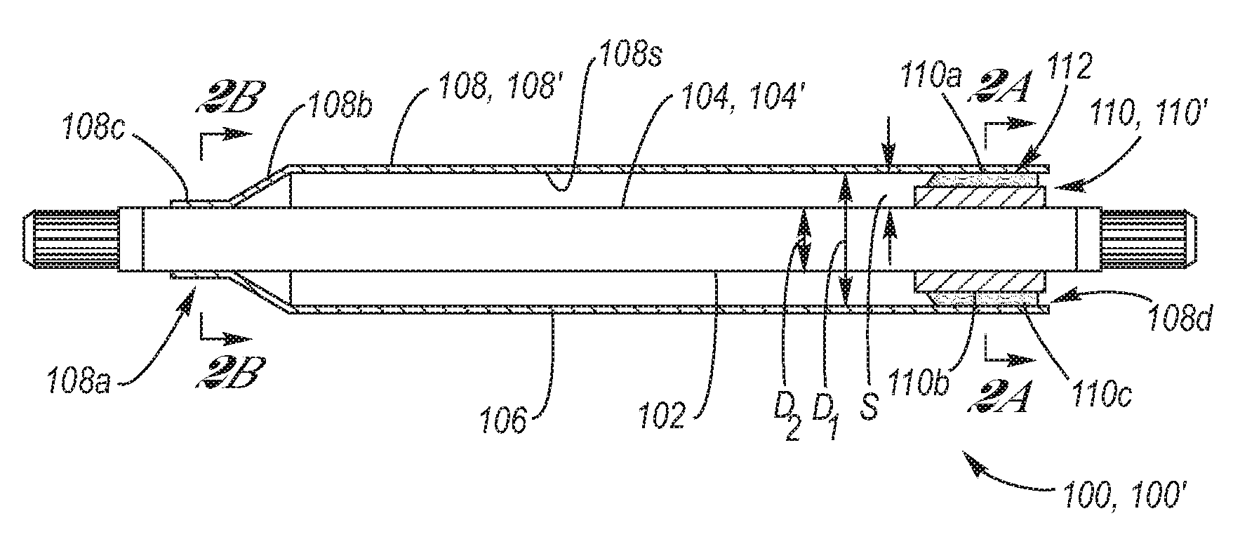
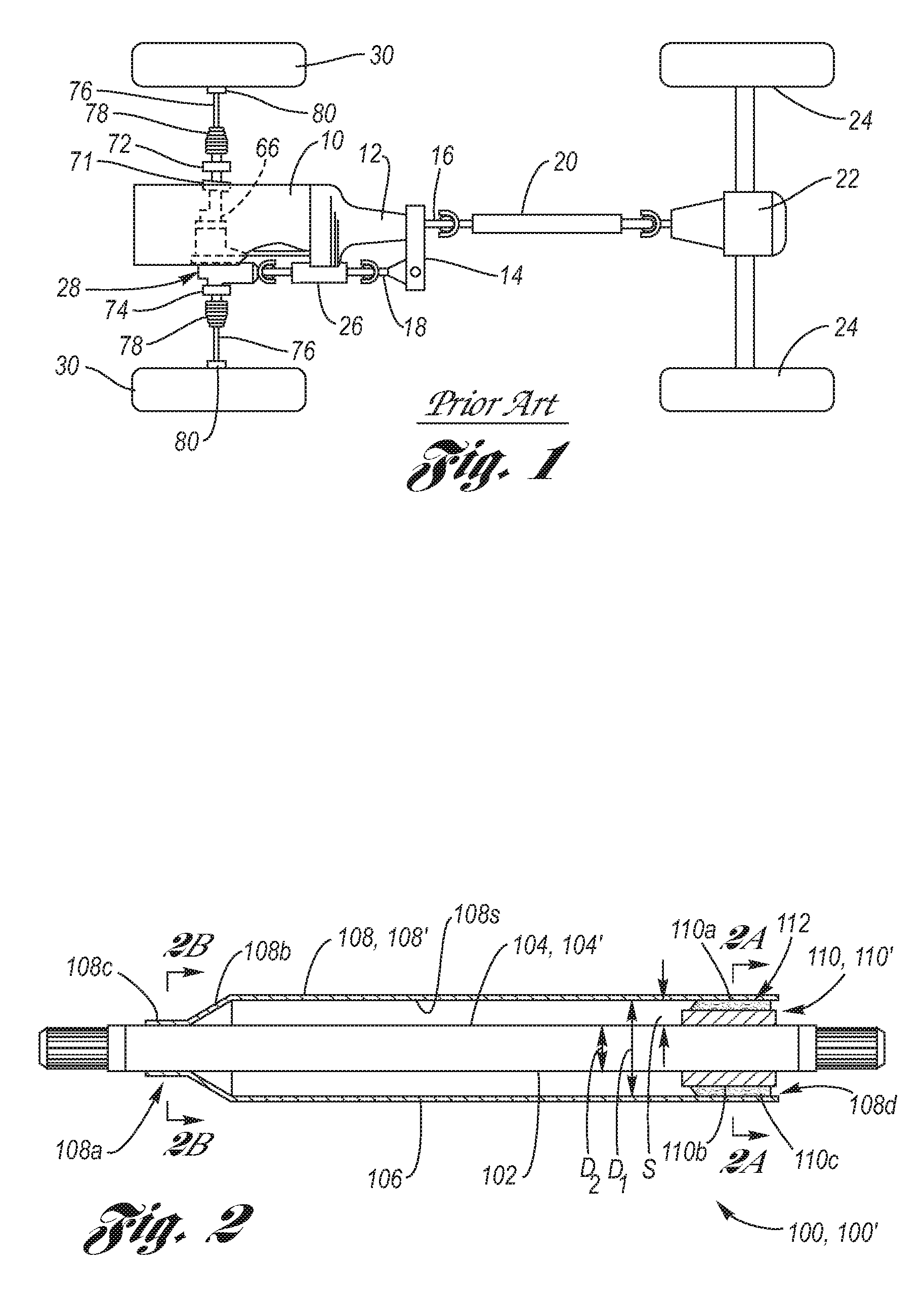
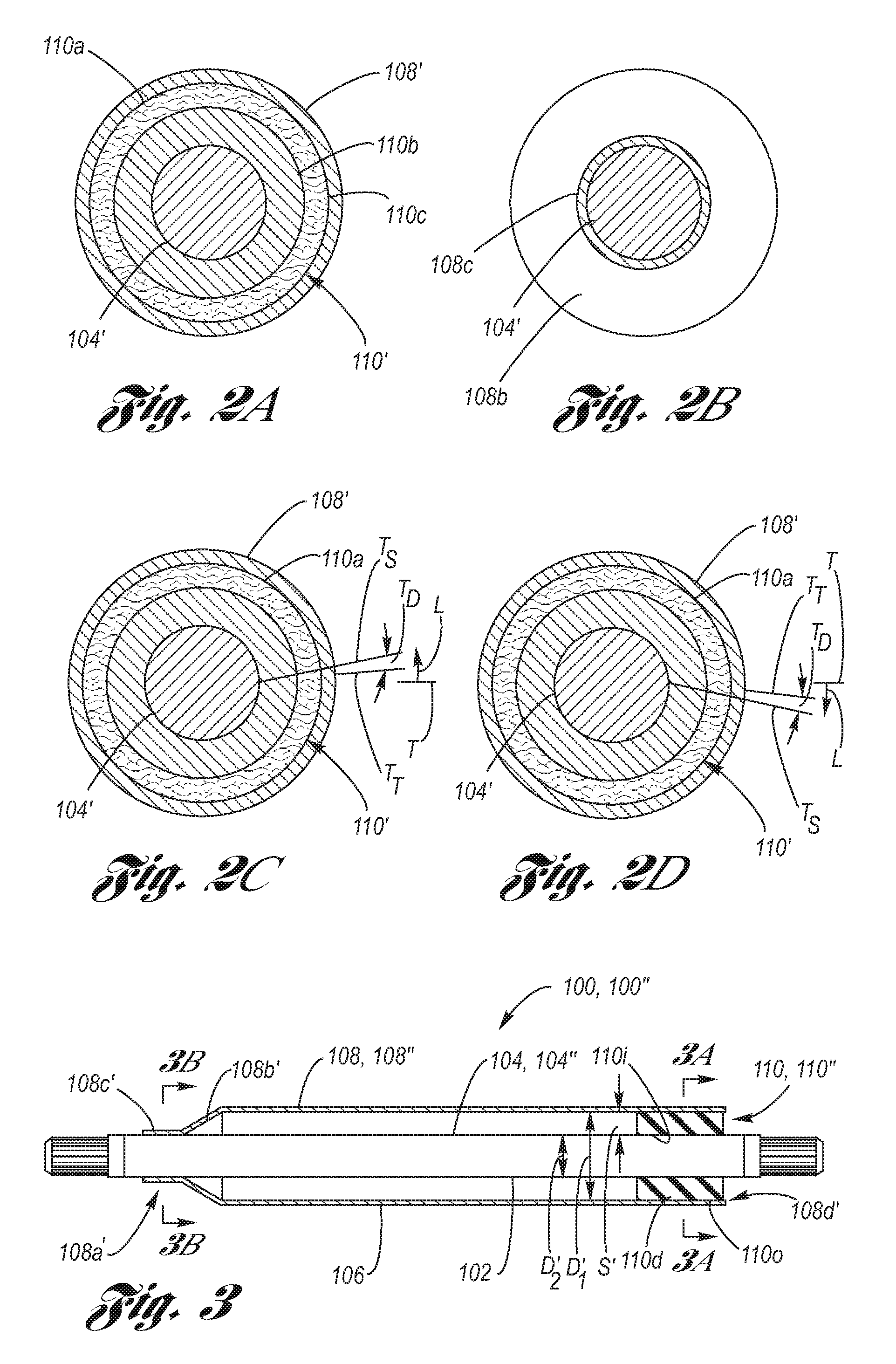
[0036]Referring now to the Drawing, FIGS. 2 through 5 depict various examples of a damped axle shaft 100 according to the present invention, wherein throughout the views, the damped axle shaft 100 is inherently damped very near the source of the oscillation, which in the case of powerhop, the source is generally the torsional wind-up of the axle shaft vis-à-vis the attendant response of the tires meeting the road surface.

[0037]The damped axle shaft 100 includes, generally, an inner axle component 102 which serves as the axle shaft 104 having a first torsional stiffness, an outer axle component 106 in the form of a cylindrical axle tube 108 which is concentrically disposed with respect to the axle shaft and generally co-terminal therewith (by the term generally co-terminal is meant generally co-terminal not inclusive of the splines, or other rotative drive interface, at each end of the axle shaft) and has a second torsional stiffness, and at least one damping ring 110 disposed betwee...


PUM

PropertyMeasurementUnit
Elasticityaaaaaaaaaa
Stiffnessaaaaaaaaaa
Frictionaaaaaaaaaa

Abstract

An axle shaft which is inherently damped very near the source of the oscillation, via inner and outer axle components with a damping ring that couples between them, wherein the inner component which serves as the axle shaft, has a torsional stiffness different from (i.e., less than) that of the outer component which serves as a concentrically disposed axle sleeve. Under torsional load, both the inner and outer components transmit the torsional load, wherein the inner component twists more than the outer component, resulting in relative displacement therebetween. The damping ring experiences the relative displacement and consequently damps energy of the twist, whereby powerhop and associated driveline disturbances, such as for example axle shutter, are reduced.

Description

TECHNICAL FIELD[0001]The present invention relates generally to drive axle shafts of motor vehicles, and more particularly to a damped axle shaft having inner and outer components which are mutually torsionally damped.BACKGROUND OF THE INVENTION[0002]Motor vehicles with driven axle independent suspensions include a pair of axle shafts (also referred to as split axles or half shafts), one for each wheel, as described, merely by way of exemplification, in U.S. Pat. No. 4,699,235 issued on Oct. 13, 1987 to Anderson and assigned to the assignee of the present patent application, the disclosure of which is hereby incorporated herein by reference.[0003]Referring now to FIG. 1, the split axle drive system of U.S. Pat. No. 4,699,235 will be briefly described for point of reference, it being understood the present invention may apply to two wheel drive or four wheel drive systems.[0004]Shown is a schematic plan view of a part-time four-wheel drive vehicle, comprising an internal combustion e...

Claims


Application Information

Patent Timeline
IPC IPC(8): F16C3/02
CPCA61K31/05A61K31/135A61K31/137A61K31/167A61K31/4164A61K31/4178Y10T464/50A61K31/5517A61K31/573A61K31/661A61K45/06F16C3/02F16F7/04A61K31/4468F16F15/10
Inventor LYSCIO, ANTHONY L.
Owner GM GLOBAL TECH OPERATIONS LLC
Why Eureka
Try Eureka