Blast movement monitor and method for determining the movement of a blast movement monitor and associated rock as a result of blasting operations

a technology of movement monitor and monitor, which is applied in the direction of instruments, surveyors, well accessories, etc., can solve the problems of no satisfactory techniques for measuring or modelling this movement, the movement of rock and therefore also the ore boundaries, and the inability to accurately determine the movement of the monitor, so as to reduce the risk of damage to the transmitter, reduce the friction between the casing and the internal wall, and damp the energy of the blast

Active Publication Date: 2005-01-20
LEICA GEOSYSTEMS PTY LTD +1
View PDF7 Cites 35 Cited by
  • Summary
  • Abstract
  • Description
  • Claims
  • Application Information

AI Technical Summary

Benefits of technology

The casing and transmitter assembly is designed to have a density that is very close to that of the liquid within which it is immersed. Ideally it has a density that is the same as the liquid within which it is immersed. When this occurs it has zero weight in the liquid and a neutral buoyancy and the casing floats in the liquid. This assists in reducing friction between the casing and the internal wall. This is important to enable the casing and transmitter to self right after each blast.
In addition the liquid may serve to damp energy from the blast and thereby reduce the risk of damage to the transmitter.

Problems solved by technology

However it is quite clear that the rock moves when it is subjected to blasting.
Currently there are no satisfactory techniques for measuring or modelling this movement in the rock and thereby also the ore boundaries as a result of the blasting operations.
The problem is that it is clear that the rock and therefore also the ore boundaries do move.
This leads to a loss of product which is intended to be recovered.
This can lead to a significant loss. of efficiency in the concentrators as it processes more waste and less product.
This can lead to a drop off in the volume of concentrate produced per unit time.
It is universally recognised that this approach is unsatisfactory.

Method used


Image

  • Blast movement monitor and method for determining the movement of a blast movement monitor and associated rock as a result of blasting operations
  • Blast movement monitor and method for determining the movement of a blast movement monitor and associated rock as a result of blasting operations
  • Blast movement monitor and method for determining the movement of a blast movement monitor and associated rock as a result of blasting operations

Examples


Embodiment Construction

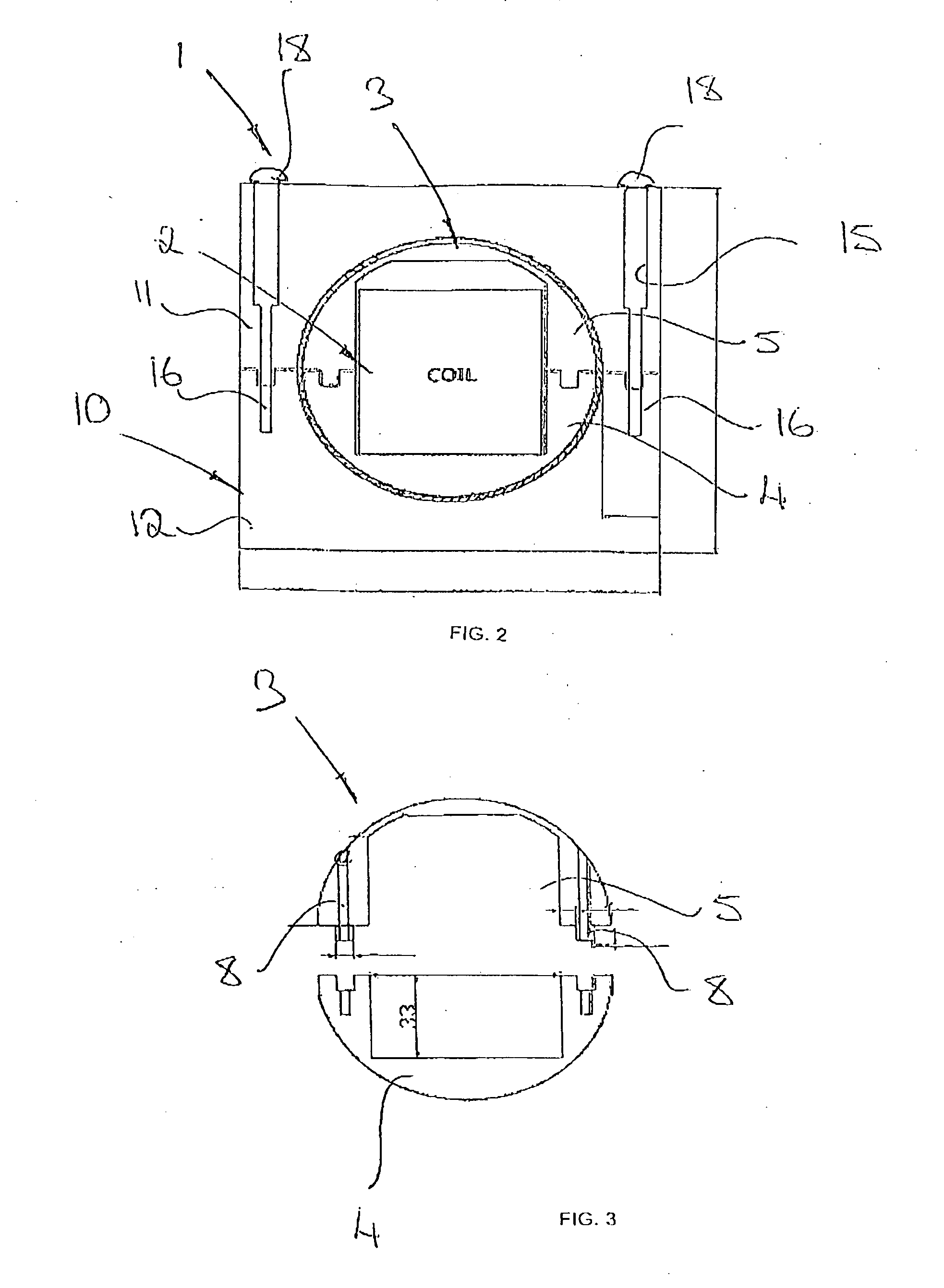
In FIGS. 2 to 4 the blast movement monitor is indicated generally by the reference numeral 1.

The monitor 1 comprises broadly a communication device that is a transmitting device or transmitter 2 received within a monitor body that is in the form of a split casing 3. The casing 3 comprises two hemispherical halves 4, 5 and may conveniently be made of a material such as nylon, polyethelene, polystyrene or other engineering plastics although clearly other materials may also be used. The transmitter 2 comprises a cylindrical coil oscillating at a suitable frequency for example 50 to 90 kHz. In the illustrated embodiment a frequency of 66 kHz was used although clearly many other frequencies could equally have been used. An advantage of using a low frequency is that it is attenuated to a lesser extent in rock. The coil is oriented vertically in the casing as shown in FIG. 2. This has the effect of generating a dipole shaped magnetic field as shown in FIG. 5 with magnetic field lines 6....


PUM


Abstract

A method for measuring the movement of boundaries between different portions of a heterogeneous rock body is disclosed. The method comprises placing a plurality of blast movement monitors 109 in a rock body prior to blasting and noting the position of each blast movement monitor. The rock body is then blasted to break it up into a plurality of pieces. Thereafter the position of the blast movement monitors 109 is located and based on this the boundaries of rock portions can be adjusted to account for the blast. This leads to a more accurate reporting of different ore bodies to the appropriate processor in a heterogeneous rock body. An apparatus for carrying out the method is also disclosed. The apparatus comprises broadly a said monitor 109 and a receiver. The monitor 1 comprises a transmitter 109 received within a casing 111 that in turn is received within a housing 126. Further the casing 111 can move within the housing 126 and self right so that it always transmits its signal in an upright direction.

Description

FIELD OF THE INVENTION This invention relates to a method for determining the movement of a blast movement monitor placed within a rock body as a result of blasting of the rock. This invention also extends to a blast movement monitor and apparatus for use in performing the method. This invention also extends to a method of determining the movement in a boundary between two different rock or ore positions in a heterogeneous rock body. This invention relates particularly but not exclusively to a method of determining the movement of an ore boundary. Typically the boundary might be between high grade ore, e.g. a vein of gold ore, and a low grade ore, in a heterogeneous ore body of an open cast mine that practises open cut selective mining. It will therefore be convenient to hereinafter describe this invention with reference to this example application. However it is to be clearly understood that the invention is capable of broader application. For example the invention may be used to...

Claims


Application Information

Patent Timeline
Patent Type & Authority Applications(United States)
IPC IPC(8): E21B47/02E21C39/00E21C41/26G01B7/14
CPCE21B47/02E21C41/26E21C39/00
Inventor LA ROSA, DAVID MARIOTHORNTON, DARREN MARKWORTLEY, MICHAEL
Owner LEICA GEOSYSTEMS PTY LTD
Why Eureka
Try Eureka