
Computer system and method for controlling the same

a computer system and computer technology, applied in the field of computer systems, can solve problems such as system complexity and invite the problem of interference between process units, and achieve the effect of not complicating

Inactive Publication Date: 2009-08-06
PANASONIC CORP
View PDF7 Cites 3 Cited by
  • Summary
  • Abstract
  • Description
  • Claims
  • Application Information

AI Technical Summary

Benefits of technology

[0006]In a conventional computer system, however, when a process unit joins or leaves the group of process units running at the same time, it is necessary to re-set the amount of allocated cache memory for all process units, and it is necessary to provide means for calculating the amounts to be re-set. This complicates the system, and invites the problem of interference between process units.
[0007]It is therefore an object of the present invention to realize a computer system capable of accommodating a change to the group of process units running at the same time without having to re-set the amount allocated cache memory.
[0009]With the computer system of the present invention, the amount of cache memory allocated for each process unit can be varied automatically without re-setting. Therefore, even when a process unit joins or leaves the group of process units running at the same time, it is not necessary to re-set the amount of allocated cache memory for all process units, and it is also not necessary to provide means for calculating the amounts to be re-set, whereby it is possible to change the amounts of allocated cache memory without complicating the system or creating interference between process units.

Problems solved by technology

This complicates the system, and invites the problem of interference between process units.

Method used


Image

  • Computer system and method for controlling the same
  • Computer system and method for controlling the same
  • Computer system and method for controlling the same

Examples


Embodiment Construction

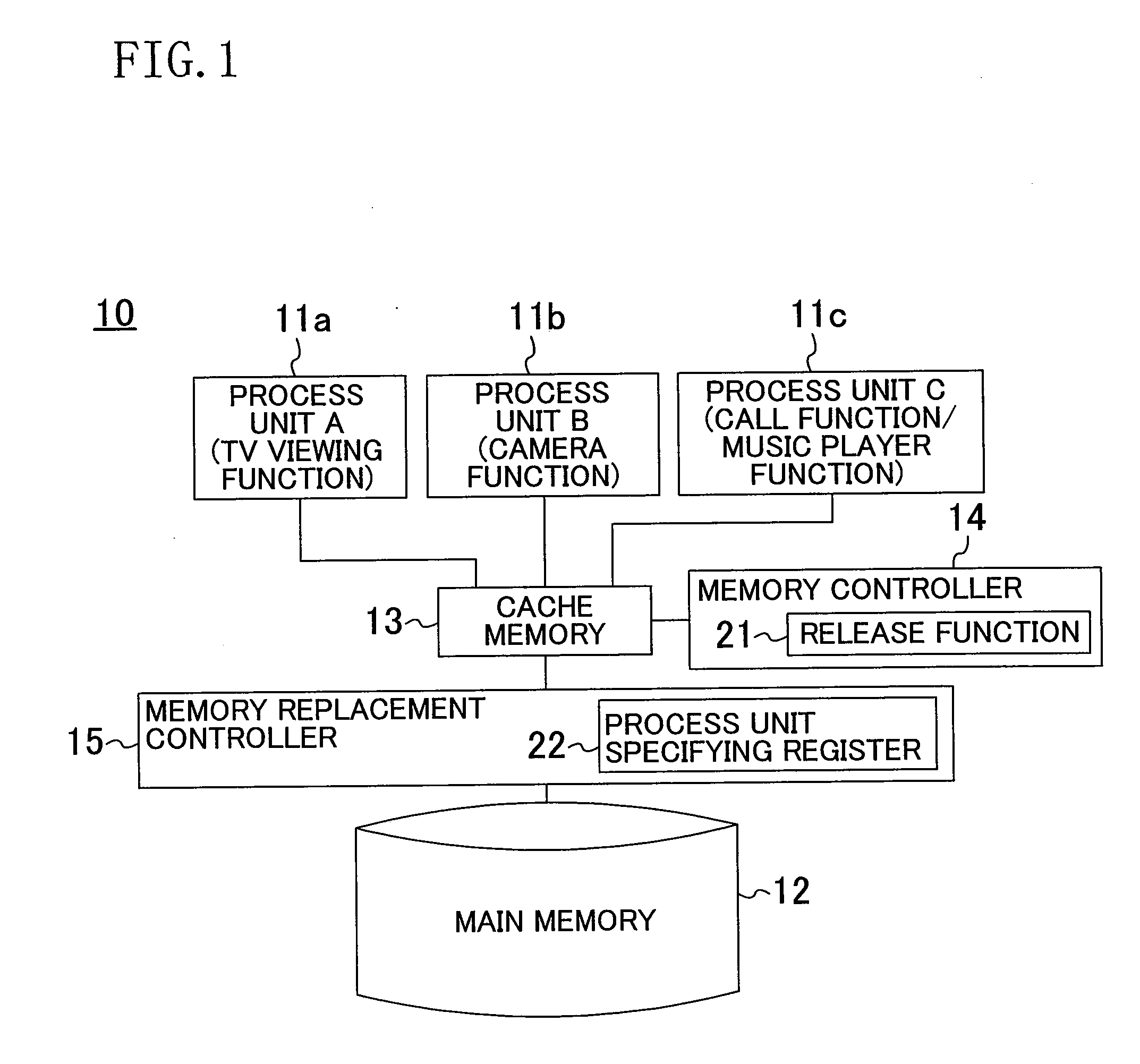
[0026]An embodiment of a computer system of the present invention will now be described with reference to the drawings.

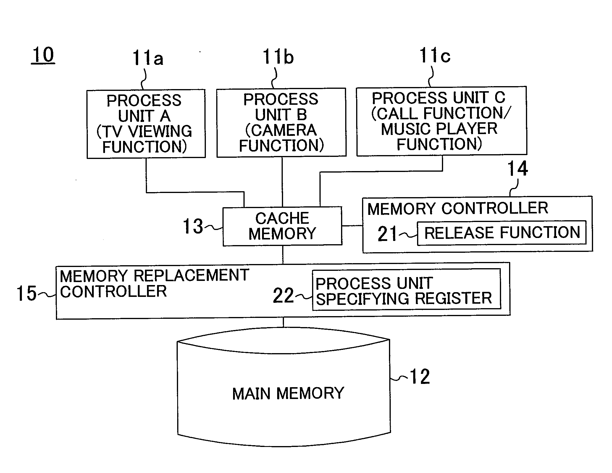
[0027]FIG. 1 shows an example of a configuration of a computer system according to the present invention. A computer system 10 of FIG. 1 includes a first process unit (Process unit A) 11a, a second process unit (Process unit B) 11b, a third process unit (Process unit C) 11c, a main memory 12, a cache memory 13, a memory controller 14, and a memory replacement controller 15.

[0028]The first, second and third process units 11a, 11b and 11c may each be hardware (a dedicated circuit) such as a processor or software such as a thread or a program. Normally, software is stored in a storage medium such as a ROM. In the present embodiment, it is herein assumed that the first, second and third process units 11a, 11b and 11c are all processors, for the sake of simplicity.

[0029]It is herein assumed that the third process unit 11c is a basic process unit for realizing the basic f...


PUM


Abstract

A computer system includes a main memory for storing a large amount of data, a cache memory that can be accessed at a higher speed than the main memory, a memory replacement controller for controlling the replacement of data between the main memory and the cache memory, and a memory controller capable of allocating one or more divided portions of the cache memory to each process unit. The memory replacement controller stores priority information for each process unit, and replaces lines of the cache memory based on a replacement algorithm taking the priority information into consideration, wherein the divided portions of the cache memory are allocated so that the storage area is partially shared between process units, after which the allocated amounts of cache memory are changed automatically.

Description

BACKGROUND OF THE INVENTION[0001]1. Field of the Invention[0002]The present invention relates to a computer system with an improved efficiency of use of a cache memory, and a method for controlling the same.[0003]2. Description of the Background Art[0004]In a conventional computer system, the number of functions (processes therefor) has been increasing, and a mechanism has been proposed in the art (see, for example, Japanese Laid-Open Patent Publication No. 9-146842 and United States Patent Application Publication No. 2007 / 0033341) in which the storage area of the cache memory, which influences the processing performance, is divided into portions, each corresponding to one process unit so as to avoid as much as possible the interference between processes.[0005]As a countermeasure against the decrease in the efficiency of use of the cache memory after being divided into portions, a technique has been proposed in the art (see, for example, U.S. Pat. No. 7,293,144) in which the cache m...

Claims


Application Information

Patent Timeline
IPC IPC(8): G06F12/08
CPCY02B60/1225G06F12/126Y02D10/00
Inventor KOGA, YOSHIHIRO
Owner PANASONIC CORP
Learn More