Actuator, parallel link mechanism using the same, and long material bending device

a technology of parallel link mechanism and bending device, which is applied in the direction of mechanical control device, instrument, gearing, etc., can solve the problems of inability to substantially reduce the dimensions of the fitting plate, inevitably increasing costs, etc., and achieves the effect of reducing the dimensions of the fitting part, enhancing safety against buckling, and reducing manufacturing costs

Inactive Publication Date: 2009-08-13
KIKUCHI SEISAKUSHO CO LTD
View PDF2 Cites 9 Cited by
  • Summary
  • Abstract
  • Description
  • Claims
  • Application Information

AI Technical Summary

Benefits of technology

[0011]The actuator according to the invention is enabled by the trunnion type universal joint of the above-described configuration to select the position of the fixed side supporting point as desired and to be compact in overall configuration of the actuator by dramatically reducing the dimensions of the fitting part of the actuator. Moreover, control items such as a driving motor and a position sensor of standard designs are enabled to be fitted around outside the actuator to reduce the manufacturing cost. Furthermore, the distance between the fixed side supporting point and the movable supporting point of the actuator can be shortened to enhance safety against buckling and increase mechanical rigidity.
[0012]The parallel link mechanism using the actuator according to the invention is enabled by the actuator of the above-described configuration to select the position of the fixed side supporting point as desired and to be compact in overall configuration of the parallel link mechanism by dramatically reducing the dimensions of the fitting part of the actuator. Moreover, control items such as a driving motor and a position sensor of standard designs are enabled to be fitted around outside the actuator to reduce the manufacturing cost. Furthermore, the distance between the fixed side supporting point and the movable supporting point of the actuator can be shortened to enhance safety against buckling and increase mechanical rigidity.
[0013]The long material bending device using the actuator according to the invention is enabled by the actuator of the above-described configuration to select the position of the fixed side supporting point, to dramatically reduce the dimensions of the fitting part of the actuator while securing a sufficient moving range for the movable die, and to reduce the size of the bending head to make the overall configuration of the bending device compact. Moreover, control items such as a driving motor and a position sensor of standard designs are enabled to be fitted around outside the actuator to reduce the manufacturing cost. Furthermore, the distance between the fixed side supporting point and the movable supporting point of the actuator can be shortened to enhance safety against buckling and increase mechanical rigidity.

Problems solved by technology

However, when a mechanism in which the middle part of a ball screw is fitted to a fitting plate (top plate) with a penetrating type universal joint as in the conventional machine tool described above is to be applied to a long material bending device shown in FIG. 1, it is possible to use a somewhat smaller top plate than in the usual fitting arrangement for the actuator (the tip of the actuator is fitted to a movable plate through a usual type universal joint and its rear end is fitted to the fitting plate through a similar universal joint) shown in FIG. 2, but it is difficult to substantially reduce the dimensions of the fitting plate where a penetrating type universal joint, whose center is penetrated by the actuator, is used because the universal joint bulges around outside the actuator and, moreover, the cost inevitably increases because control items such as a driving motor and a position sensor of standard designs cannot be fitted around the actuator.

Method used


Image

  • Actuator, parallel link mechanism using the same, and long material bending device
  • Actuator, parallel link mechanism using the same, and long material bending device
  • Actuator, parallel link mechanism using the same, and long material bending device

Examples


Embodiment Construction

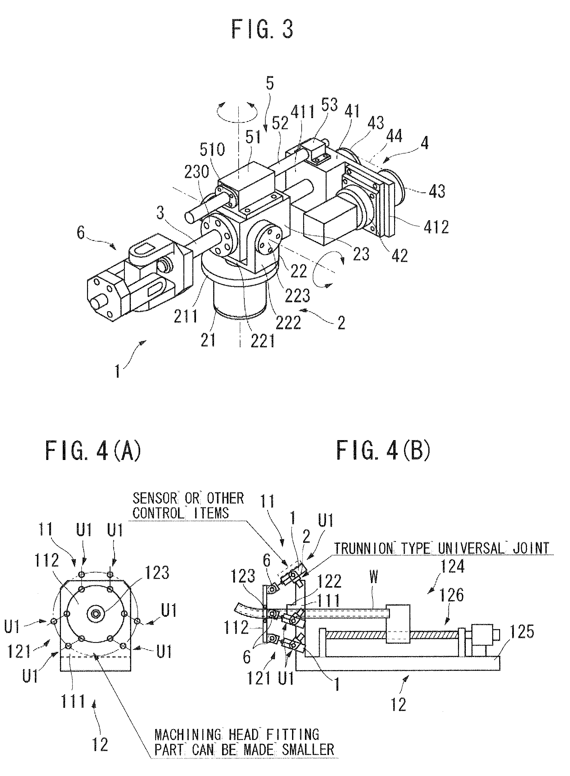
[0020]A preferred embodiment of the present invention will be described below with reference to drawings. FIG. 3 shows a perspective view of the configuration of an actuator, which is the embodiment of the invention. Referring to FIG. 3, an actuator 1 is provided with a trunnion type universal joint 2, a ball screw 3, a driving unit 4 for a ball screw and a ball screw guide 5 as its basic constituent elements, each of which will be described in detail below.

[0021]The trunnion type universal joint 2 includes a fitting shaft 21, a holding member 22 and a rotary block 23. In this case, the fitting shaft 21 includes a cylindrical member having a flange 211 at its upper end (one end), and a bearing is arranged on its inner circumferential face. This fitting shaft 21 may have any external shape, such as a rectangular shape. The holding member 22, formed of a groove-shaped member, has a base 221 in the middle and a holding part 222 on each side of it. A shaft (not shown) is fixed downward ...


PUM

PropertyMeasurementUnit
degrees of freedomaaaaaaaaaa
rotational angleaaaaaaaaaa
degrees of freedomaaaaaaaaaa

Abstract

The dimensions of the fitting part of an actuator are to be dramatically reduced while enabling control items such as a driving motor and a position sensor of standard designs to be fitted around outside the actuator. To achieve this purpose, the actuator is provided with a trunnion type universal joint including: a fitting shaft, holding members and a rotary block having a nut arranged in it; a ball screw that is screwed into the nut of the universal joint and, being operationally linked to a driving power source, can move the nut back and forth; and a ball screw guide that is provided on the universal joint and guides the back-and-forth moving direction of the ball screw.

Description

BACKGROUND OF THE INVENTION[0001]1. Field of the Invention[0002]The present invention relates to a ball screw type actuator suitable for use in machining pipes, rods and shapes, a parallel link mechanism using the same, and a long material bending device.[0003]2. Description of the Related Art[0004]Actuators of this kind, parallel link mechanisms using one or another of such actuators, and various machine tools have been known. One example is disclosed in Patent Document 1. This machine tool includes a frame, a table to mount a work on, a main shaft head for holding a tool, plural driving devices (actuators) for driving the main shaft head with a ball screw, and an NC device for controlling the driving devices. In this particular machine tool, the middle part of the ball screw is supported by a penetrating type universal joint to permit inclination relative to the top plate of the frame, and the tip of the ball screw is directly linked to a universal joint to permit inclination rela...

Claims


Application Information

Patent Timeline
Patent Type & Authority Applications(United States)
IPC IPC(8): F16H25/20F16H21/10B21D5/06B21D5/00
CPCB21D7/025Y10T74/20207Y10T74/18656F16H25/20
Inventor SATO, SHINJIROICHIRYU, KENHACHINOHE, TAKUYA
Owner KIKUCHI SEISAKUSHO CO LTD
Why Eureka
Try Eureka