Storage container

a storage container and temperature control technology, applied in the direction of containers, domestic cooling devices, caps, etc., can solve the problems of increasing the running cost, not only the amount of solid carbon dioxide, and taking a lot of trouble for refilling solid carbon dioxide, so as to reduce the possibility of forming gaps and enhance the insulating performance of storage containers.

Inactive Publication Date: 2009-08-13
TWINBIRD CORP
View PDF4 Cites 18 Cited by
  • Summary
  • Abstract
  • Description
  • Claims
  • Application Information

AI Technical Summary

Benefits of technology

[0010]Thus, in order that the temperature control effect member of the temperature control subunit may be thermally exposed inside the insulating container, the temperature controlling unit that is independent of the insulating container is detachably attached to the opening of the insulating container in a manner closing and sealing a portion of the opening, while the main lid is openably and closably attached to an other portion of the opening to thereby constitute the storage container, whereby the interior of the container is cooled. Further, as any arbitrary sizes of the insulating container and the main lid may be chosen as long as they are within a range that allows the temperature controlling unit to be attached thereto, it is possible to set a volume of the storage container relatively freely. Furthermore, as the interior space defined by the insulating container and the lid is cooled by the temperature controlling unit, items to be stored can be stored for a longer period of time. Moreover, as solid carbon dioxide, etc. is not used in cooling the interior of the storage container by the temperature controlling unit, the running cost thereof can be reduced, and environmental burden can be suppressed as gasified carbon dioxide is not generated. Additionally, the temperature controlling unit can be simply formed by fitting the base provided on the temperature controlling subunit into the through-hole of the sub-lid. In addition to the foregoing, as the interior of the storage container is cooled by the Stirling refrigerator, the interior of the storage container can be cooled to a very low temperature at a low running cost, and the container as a whole can relatively have a light-weight structure.
[0030]Thus, the step member of the main lid contacts the step member of the sub-lid, thereby reducing the possibility of forming a gap between the main lid and the sub-lid, and thus the insulating performance of the storage container can be enhanced.

Problems solved by technology

The container which cools the interior by solid carbon dioxide, a cold reserving agent or the like, however, has a problem such that as solid carbon dioxide sublimes or the cold reserving agent melts down due to heat from stored items or heat from the exterior of the container, it takes a lot of trouble for refilling solid carbon dioxide or replacing the cold reserving agent to keep the stored items in the container for a long time.
In the case of using solid carbon dioxide, its repetitive use over a long period of time increases not only the amount of the solid carbon dioxide, which eventually increases the running cost, but also the density of carbon dioxide in the atmosphere as the solid carbon dioxide gasifies due to the sublimation.
While the containers of the above described Japanese publications neither require such a labor nor suffer such an environmental burden, they are unable to store items with larger volumes than the internal volumes of the containers due to the pre-limited inner volumes, and they are relatively heavy and expensive.
Accordingly, there is a problem in using them for transportation.

Method used


Image

  • Storage container
  • Storage container
  • Storage container

Examples


first embodiment

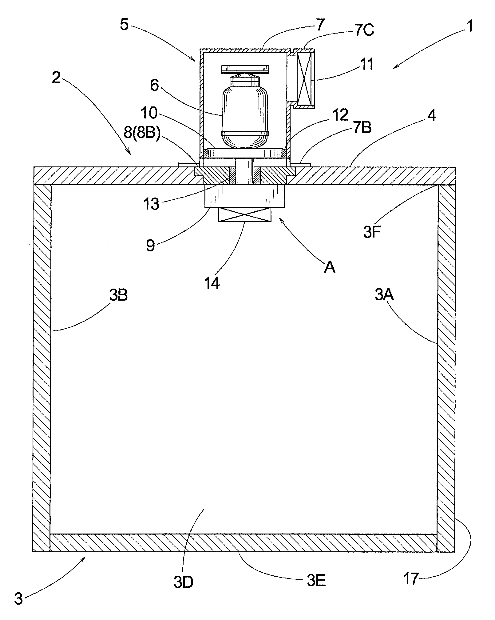
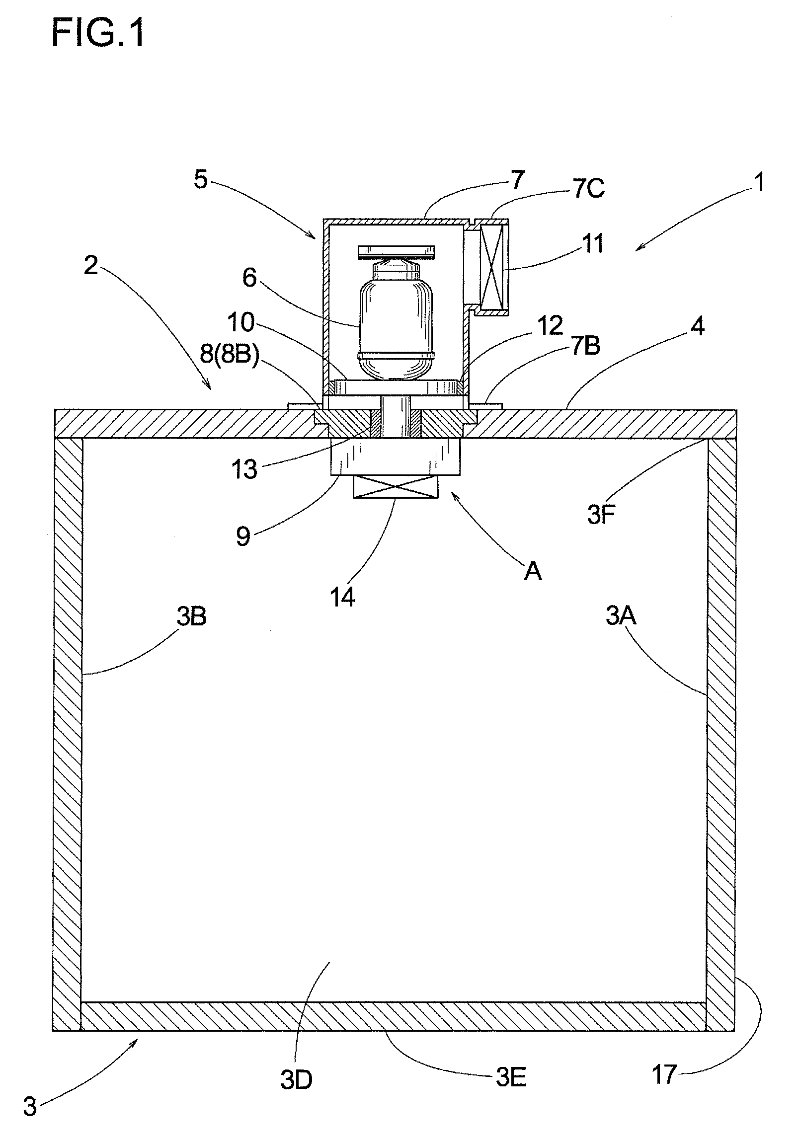
[0053]the present invention will now be explained with reference to FIGS. 1 to 4. Reference number 1 denotes a storage container, and the storage container 1 comprises a temperature controlling unit 2 and an insulating container 3.

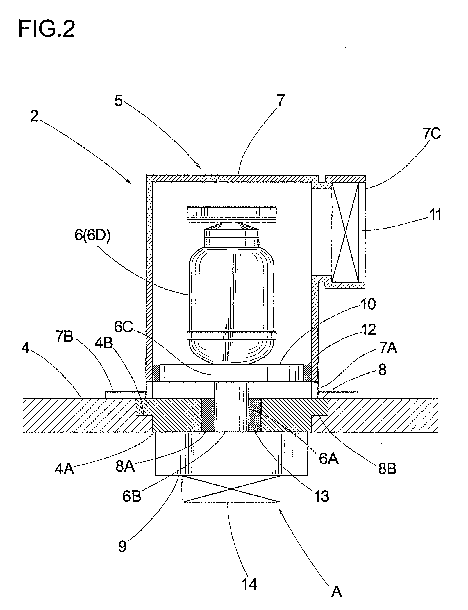
[0054]The temperature controlling unit 2 comprises a lid 4 formed with a through-hole 4A in a substantial center thereof, and a temperature controlling subunit 5. The lid 4 is made of an insulative foam synthetic resin in a tabular shape, in a single-piece manner, and its entire surface is covered with an infrared reflection film as an infrared reflection layer. A step member 4B is formed on the through-hole 4A, and a later described base 8 of the temperature controlling subunit 5 is placed on the step member 4B. The temperature controlling subunit 5 comprises a Stirling refrigerator 6 as a temperature controlling device, a casing 7 for containing the Stirling refrigerator 6, and the base 8 for supporting the Stirling refrigerator 6 and the casing 7. The S...

second embodiment

[0060]Next, how to assemble the temperature controlling unit 21 of the second embodiment will now be explained. First, the temperature controlling subunit 23 is assembled. To be more precise, the heat exhausting sink 10 is attached to the heat exhausting portion 6C of the Stirling refrigerator 6, the heat conductive block 26 is attached to the heat absorbing portion 6B of the cylindrical portion 6A, and the outer circumferences of the heat absorbing portion 6B and the heat conductive block 26 are covered with the insulating material 28 and the sealing member 29. The sealing member 12 is attached to the circumference of the heat exhausting sink 10, the Stirling refrigerator 6 is laterally accommodated in the casing 24. At this time, the heat conductive block 26 is allowed to pass through the through-hole 24D. The fan 11 is attached to the exhausting opening 24C of the casing 24. The casing 24 accommodating the Stirling refrigerator 6 is attached to the base 25 by the attachment membe...

third embodiment

[0063]Next, the present invention will now be explained with reference to FIG. 6. The same structure portions as the aforementioned embodiments are denoted by the same reference numbers, and explanations thereof will be omitted. Explanations of the similar effectiveness will be also omitted here. Reference number 30 denotes a storage container, and the storage container 30 comprises a temperature controlling unit 31 and a lid 32. The lid 32 is made of an insulative foam synthetic resin in a tabular shape, in a single-piece manner, and its entire surface is covered with an infrared reflection film as an infrared reflection layer. The lid 32 is openably and closably attached to an opening 33F of a later described insulating container 33 which constitutes the temperature controlling unit 31.

[0064]The temperature controlling unit 31 comprises an insulating container 33 and the temperature controlling subunit 23. The insulating container 33 is so structured as to include a right wall 33A...


PUM


Abstract

A storage container includes an insulating container having an opening; a temperature controlling unit that is independent of the insulating container and detachably attached to the opening of the insulating container in a manner closing and sealing a portion of the opening; and a main lid attached to the opening of the insulating container in a manner closing and sealing an other portion of the opening. The temperature controlling unit is composed of an insulative sub-lid; and a temperature controlling subunit provided on the sub-lid. The temperature controlling subunit is composed of a base fitted into a through-hole formed on the sub-lid; and a Stirling refrigerator including a temperature control effect member thermally exposed inside the insulating container. Accordingly, the interior of the insulating container of an arbitrary size can be cooled, and items can be continuously stored longer than when using conventional solid carbon dioxide or cold reserving agent.

Description

CROSS-REFERENCE TO RELATED APPLICATIONS[0001]This application is a Continuation-in-Part of U.S. Non-Provisional application Ser. No. 11 / 185,050, filed on Jul. 20, 2005, the benefit of which is hereby claimed under 35 U.S.C. § 120, and is further incorporated herein by reference. This application also claims priority to Japanese patent application No. JP2004-242952 filed on Aug. 23, 2004 and No. JP2004-278464 filed on Sep. 24, 2004, which both are herein incorporated by reference in its entirety.BACKGROUND OF THE INVENTION[0002]1. Field of the Invention[0003]The present invention relates to a temperature controlling unit and a storage container using the same, and more particularly, to a storage container for transportation.[0004]2. Description of the Related Art[0005]In general, a conventional container for transportation comprises an insulating container and a cover, both made of foam synthetic resins, and holds solid carbon dioxide, a cold reserving agent or the like inside, there...

Claims


Application Information

Patent Timeline
Patent Type & Authority Applications(United States)
IPC IPC(8): B65D81/38F25B9/00F25D11/00B65D51/00
CPCF25B9/14F25D11/00F25D2323/061F25D19/02F25D19/003
Inventor SAITO, RYOSUKENOMIZU, TOSHIKATSUODA, KIYOTAKASUZUKI, TAKESHI
Owner TWINBIRD CORP
Why Eureka
Try Eureka