Manually Rotatable Tool

a tool and rotor technology, applied in cutting machines, slitting machines, surface mining, etc., can solve problems such as the assembly of tools being a degradation

Inactive Publication Date: 2009-08-13
SCHLUMBERGER TECH CORP
View PDF99 Cites 20 Cited by
  • Summary
  • Abstract
  • Description
  • Claims
  • Application Information

AI Technical Summary

Benefits of technology

[0005]In one aspect of the present invention, a tool assembly comprises a rotary portion and a stationary portion. The rotary portion comprises a bolster bonded to a diamond, symmetric, substantially conically shaped tip. The stationary portion comprises a block mounted to a driving mechanism. A compressible element is disposed intermediate and in mechanical contact with both the rotary and stationary portions. The compressible element is compressed sufficiently to restrict free rotation during a degradation operation In some embodiments, the compressible element is compressed sufficiently enough to prevent free rotation. The tool assembly may be a degradation assembly.

Problems solved by technology

The tool assembly may be a degradation assembly.

Method used


Image

  • Manually Rotatable Tool
  • Manually Rotatable Tool
  • Manually Rotatable Tool

Examples


Embodiment Construction

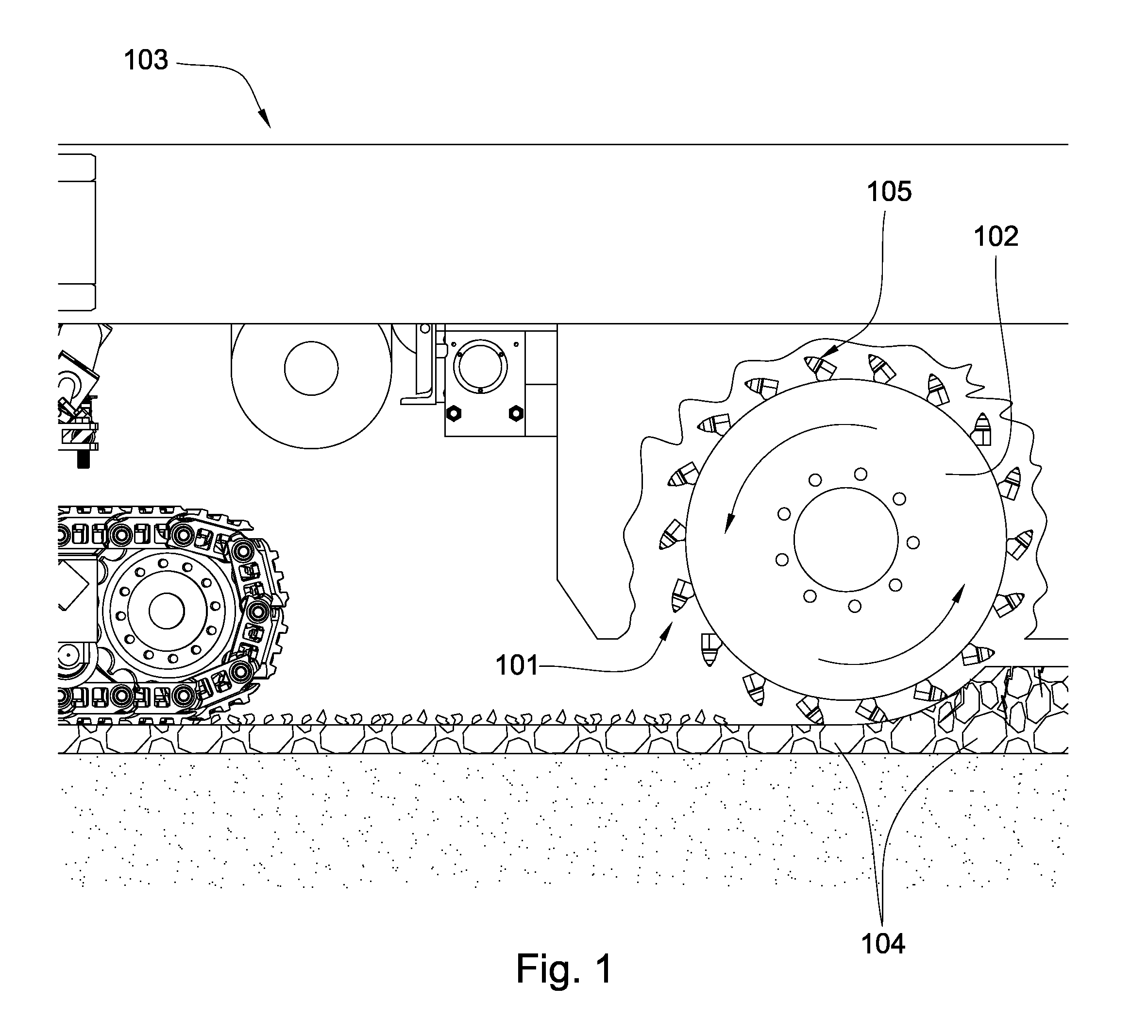
[0040]FIG. 1 is a cross-sectional diagram that shows a plurality of degradation assemblies 101 attached to a driving mechanism 102, such as a rotatable drum attached to the underside of a pavement milling machine 103. The milling machine 103 may be an asphalt planer used to degrade manmade formations such as pavement 104 prior to placement of a new layer of pavement. The degradation assemblies 101 may be attached to the drum 102, bringing the degradation assemblies 101 into engagement with the formation 104. The degradation assembly 101 may be disposed within a block 105 welded or bolted to the drum attached to the driving mechanism 102. A holder may be disposed intermediate the degradation assembly 101 and the block 105. The block 105 may hold the degradation assembly 101 at an angle offset from the direction of rotation, such that the degradation assembly engages the formation 104 at a preferential angle. While an embodiment of a pavement milling machine 103 was used in the above ...


PUM


Abstract

In one aspect of the present invention, a tool assembly comprises a rotary portion and a stationary portion. The rotary portion comprises a bolster bonded to a diamond symmetric, substantially conically shaped tip. The stationary portion comprises a block mounted to a driving mechanism. A compressible element is disposed intermediate and in mechanical contact with both the rotary and stationary portions. The compressible element is compressed sufficiently to restrict free rotation during a degradation operation.

Description

CROSS REFERENCE TO RELATED APPLICATIONS[0001]This application is a continuation of U.S. patent application Ser. No. 12 / 428,531 which is a continuation-in-part of U.S. patent application Ser. No. 12 / 177,556 which is a continuation-in-part of U.S. patent Ser. No. 12 / 135,595 which is a continuation-in-part of U.S. patent Ser. No. 12 / 112,743 which is a continuation-in-part of U.S. patent application Ser. No. 12 / 051,738 which is a continuation-in-part of U.S. patent application Ser. No. 12 / 051,689 which is a continuation of U.S. patent application Ser. No. 12 / 051,586 which is a continuation-in-part of U.S. patent application Ser. No. 12 / 021,051 which is a continuation-in-part of U.S. patent application Ser. No. 12 / 021,019 which was a continuation-in-part of U.S. patent application Ser. No. 11 / 971,965 which is a continuation of U.S. patent application Ser. No. 11 / 947,644, which was a continuation-in-part of U.S. patent application Ser. No. 11 / 844,586. U.S. patent application Ser. No. 11 / 8...

Claims


Application Information

Patent Timeline
Patent Type & Authority Applications(United States)
IPC IPC(8): E21C35/18E21C41/00E21C35/183E21C35/197E21C35/19
CPCE21C35/197E21C35/183
Inventor HALL, DAVID R.CROCKETT, RONALD B.PETERSON, GARYJEPSON, JEFF
Owner SCHLUMBERGER TECH CORP
Why Eureka
Try Eureka