Locking instrument assembly

a technology of locking instruments and parts, applied in the field of orthopaedic cutting instruments, can solve the problems of limiting the amount of stability achieved, unable to control the freedom of previous devices, and unable to be relatively accessible, so as to reduce the need for secondary fixation devices.

Active Publication Date: 2009-08-13
SMITH & NEPHEW INC
View PDF22 Cites 108 Cited by
  • Summary
  • Abstract
  • Description
  • Claims
  • Application Information

AI Technical Summary

Benefits of technology

[0027]The invention has several advantages over prior devices and techniques. For example, by adding the ability to rotate the cutting guide on either a reference axis or an established secondary axis, the surgeon is able to maneuver the resection instrumentation around obstructions or clearance issues. By the ability t

Problems solved by technology

However, these previous devices do not control all degrees of freedom.
These previous devices are not stable nor are they relatively accessible.
This method restricts the amount of stability achieved to what is derived from the preset-length intramedullary instruments.
Typically, the intramedullary o

Method used


Image

  • Locking instrument assembly
  • Locking instrument assembly
  • Locking instrument assembly

Examples


second embodiment

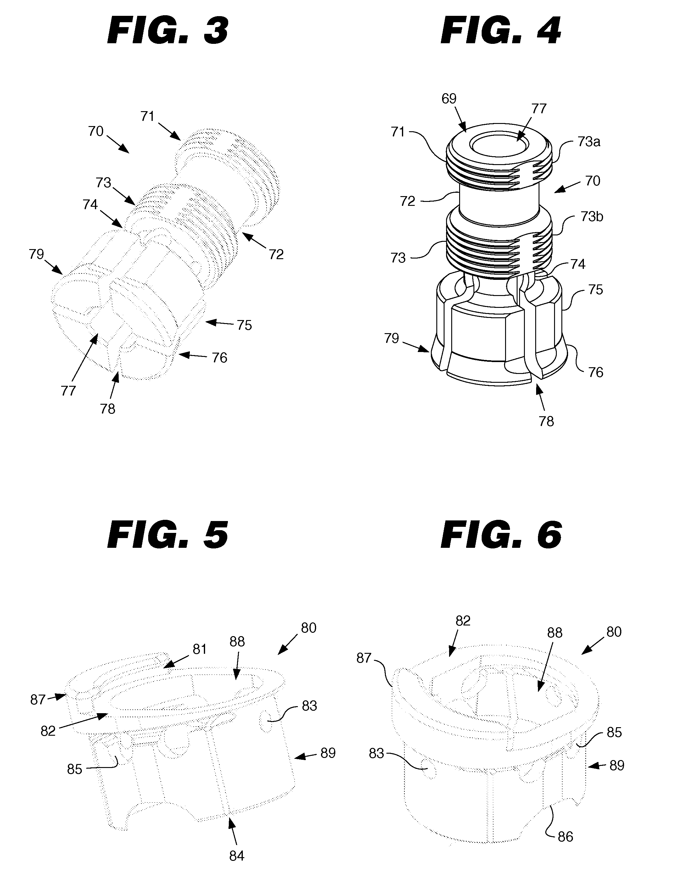
[0115]FIGS. 3 and 4 illustrate the inner collet. The inner collet 70 includes a first end portion 76, a second end portion 71, and a longitudinally extending inner bore 77. The first end portion 76 has a collar 79 and a base portion 75. The base portion 75 may be cylindrical, oval, or cylindrical with tangent portions removed. In the depicted embodiment, the base portion 75 is generally cylindrical, and the inner bore 77 is substantially coaxial with the base portion 75.

[0116]Inner collet 70 functions as a collet or wedge. The collar 79 may include one or more relief areas 78. The relief areas 78 allow a portion of the inner bore 77 to at least partially collapse. In some embodiments, the relief area 24 has a keyhole shape. The second end portion 71 has a fastener member 73. In the embodiment depicted in FIG. 3, the fastener member 73 is a helical groove or thread, but those of ordinary skill in the art would understand that other types of fastening mechanisms may be used. The faste...

third embodiment

[0140]FIGS. 40, 41, and 42 illustrate the locking instrument assembly. The locking instrument assembly 400 includes an inner collet 412, an outer body 430, a handle 456, a fastener 458, a knob 460, and a washer 464. The fastener 458 and the washer 464 are used to mount the handle 456 to the inner collet 412.

[0141]FIGS. 43 and 44 illustrate the inner collet 412. The inner collet 412 has a first end portion 414, a second end portion 416, and a longitudinally extending inner bore 418. The inner bore 418 is adapted to receive the intramedullary device 100. In other words, the inner bore 418 is shaped to fit the intramedullary device 100. The first end portion 414 has a collar 420 and a base portion 426. The base portion 426 may be cylindrical, oval, or cylindrical with tangent portions removed. In the depicted embodiment, the base portion 426 is generally cylindrical. In contrast to the previous embodiments, the inner bore 418 is offset from the central axis of the base portion 426. In ...


PUM


Abstract

A locking instrument assembly for use in conjunction with an intramedullary device is disclosed. The locking instrument assembly includes an inner collet, an outer body, and a knob. The inner collet has a collar and a fastener member. The knob engages the fastener member to press the outer body against the collar. As the knob mates with the fastener member, the collar applies a clamping force to the intramedullary device.

Description

CROSS-REFERENCE TO RELATED APPLICATIONS[0001]This application claims the benefit of International Application PCT / US06 / 38859 filed Oct. 3, 2006 which in turn claims the benefit of U.S. Provisional Application No. 60 / 723,228, filed Oct. 3, 2005 and U.S. Provisional Application No. 60 / 725,345, filed Oct. 11, 2005. The disclosure of each application is incorporated by reference in its entirety.BACKGROUND OF THE INVENTION[0002]1. Field of the Invention[0003]This invention relates generally to orthopaedic instrumentation and, more particularly, to orthopaedic cutting instruments.[0004]2. Related Art[0005]Most orthopedic instruments rely on bone spikes or pins for fixation. Other instruments use an intramedullary (IM) instrument with coupling configurations for the purpose of instrument correlation. However, these previous devices do not control all degrees of freedom. These previous devices are not stable nor are they relatively accessible.[0006]Other instruments connect to a preset-leng...

Claims


Application Information

Patent Timeline
IPC IPC(8): A61B17/56
CPCA61B17/154A61B17/1717A61B2017/00477Y10T279/17504Y10T279/17299Y10T279/17538A61B17/1764
Inventor DEES, JR., ROGER RYANYEAGER, JEFFREY N.
Owner SMITH & NEPHEW INC
Why Eureka
Try Eureka