Tuned resonant circuits

a resonant circuit and circuit block technology, applied in the field of resonant circuits, can solve problems such as system damage, resonant frequency shift from the intended frequency, and detuned tag may not derive enough power to opera

Active Publication Date: 2011-10-06
SUREFLAP
View PDF2 Cites 19 Cited by
  • Summary
  • Abstract
  • Description
  • Claims
  • Application Information

AI Technical Summary

Benefits of technology

[0065]In some preferred embodiments the MOSFET used in a non-linear capacitor is turned on or off for the full duration of the tuning cycle. This is achieved by setting the gate of this MOSFET to a high or a low voltage. This has the advantage that the non-linear capacitor behaves as a linear capacitor, taking on one of its extremal values. In some alternative embodiments the gate of the MOSFET may be instead set to zero volts, which results in a percentage ‘on time’ of the MOSFET in the region of 50%. Although the resonator does not finish in a state that has the properties of a linear resonator, the final state of the resonator may have a beneficial tuning. In particular it may ramp up to an operating level without requiring further charging of its MOSFET gate.

Problems solved by technology

This makes the system susceptible to degradation due to detuning as follows:1) Environmental detuning can cause the resonant frequency to shift from the intended frequency.
When read at a fixed frequency by the reader then the detuned tag may not derive sufficient power to operate.2) Variation at manufacture of the resonator components (generally an antenna and capacitor) has a similar effect to environmental detuning and the detuned tag may not derive sufficient power to operate.3) Mutual coupling between tags can cause their resonant frequencies to shift.
The result is again that the detuned tag may not derive sufficient power to operate.
If high levels of detuning need to be tolerated then this limits the Q of the resonator and the range of the tag decreases.
However, the accuracy of the resonator components need to be high and this increases the cost of manufacture.
However, to date this has had limited application in a conventional passive tag.
When the tag is detuned it cannot derive the power required to operate a conventional tuning circuit and therefore fails to power up.
However, the use of a separate tuning circuit that is switched in instead of the self-adaptive resonator does have some drawbacks.
These are:1) A separate tuning circuit will require additional silicon area that can lead to increases in the cost of the chip used in the RFID tag.2) The correct setting for the tuning circuit will need to be determined.
For example monitoring the envelope of the resonance as a function of the tuning setting takes time, power, and increases the complexity of the silicon.
This may increase the cost of the solution and also increase the time required until the tag is in a position to operate fully.

Method used


Image

  • Tuned resonant circuits
  • Tuned resonant circuits
  • Tuned resonant circuits

Examples


Embodiment Construction

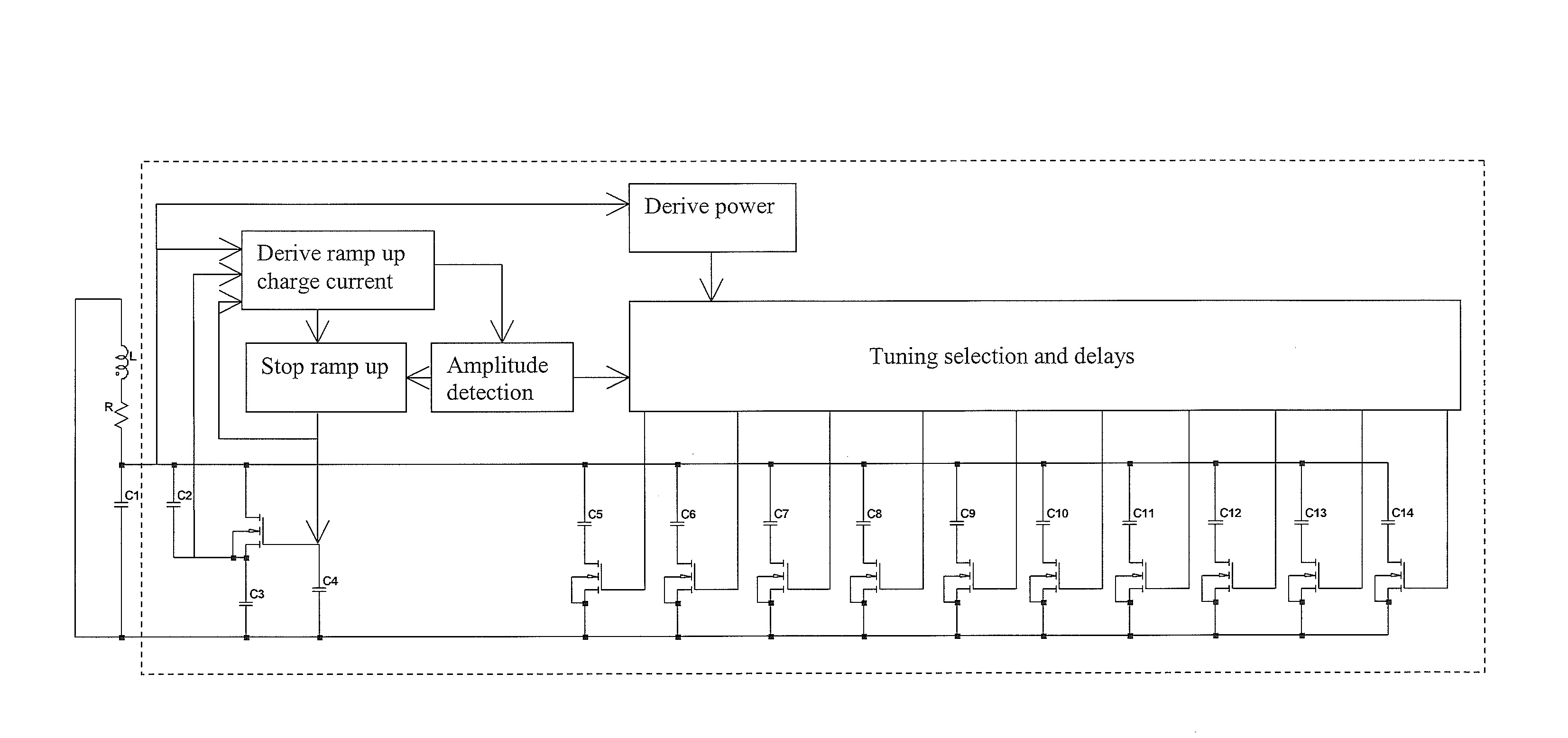
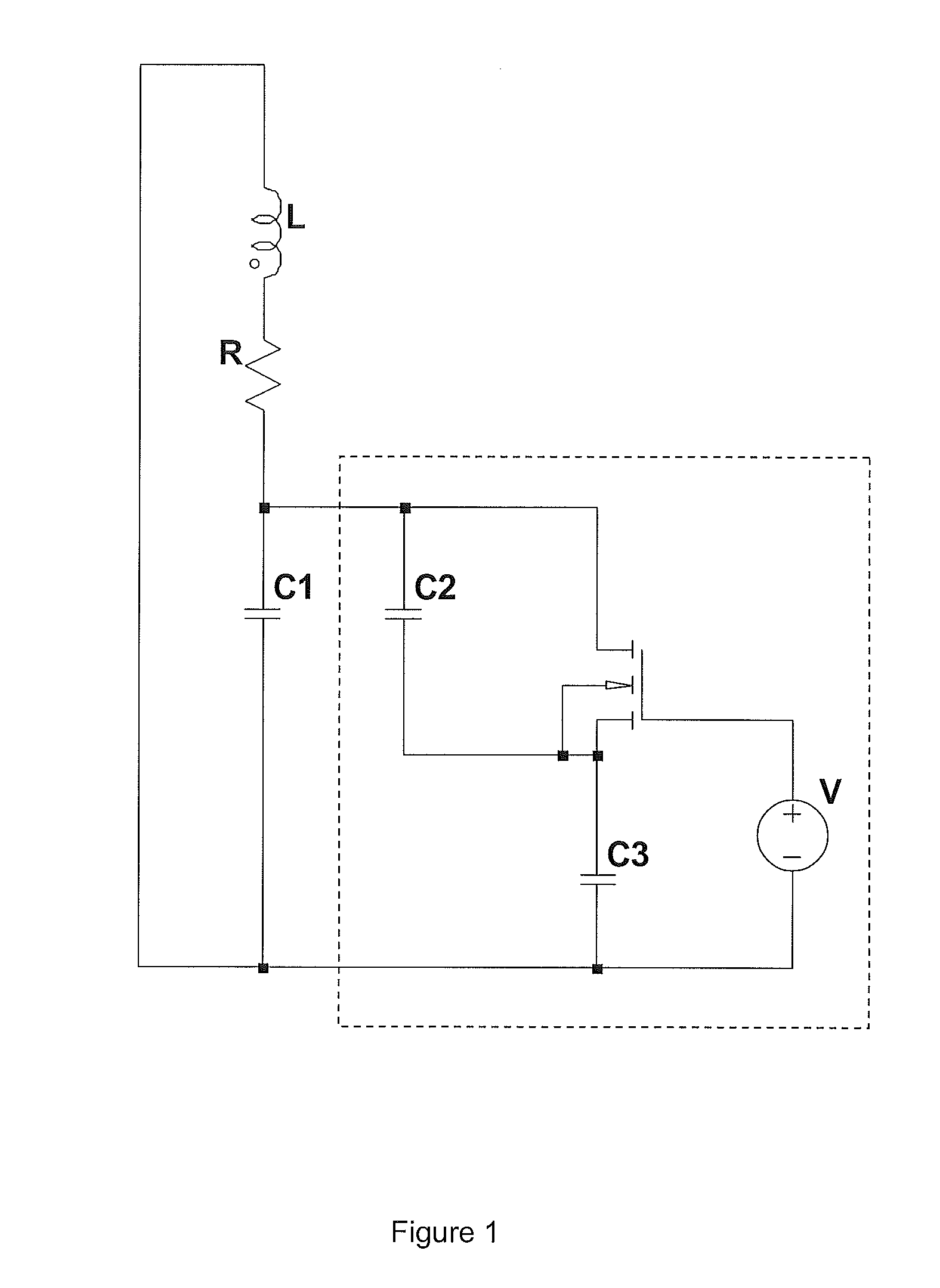
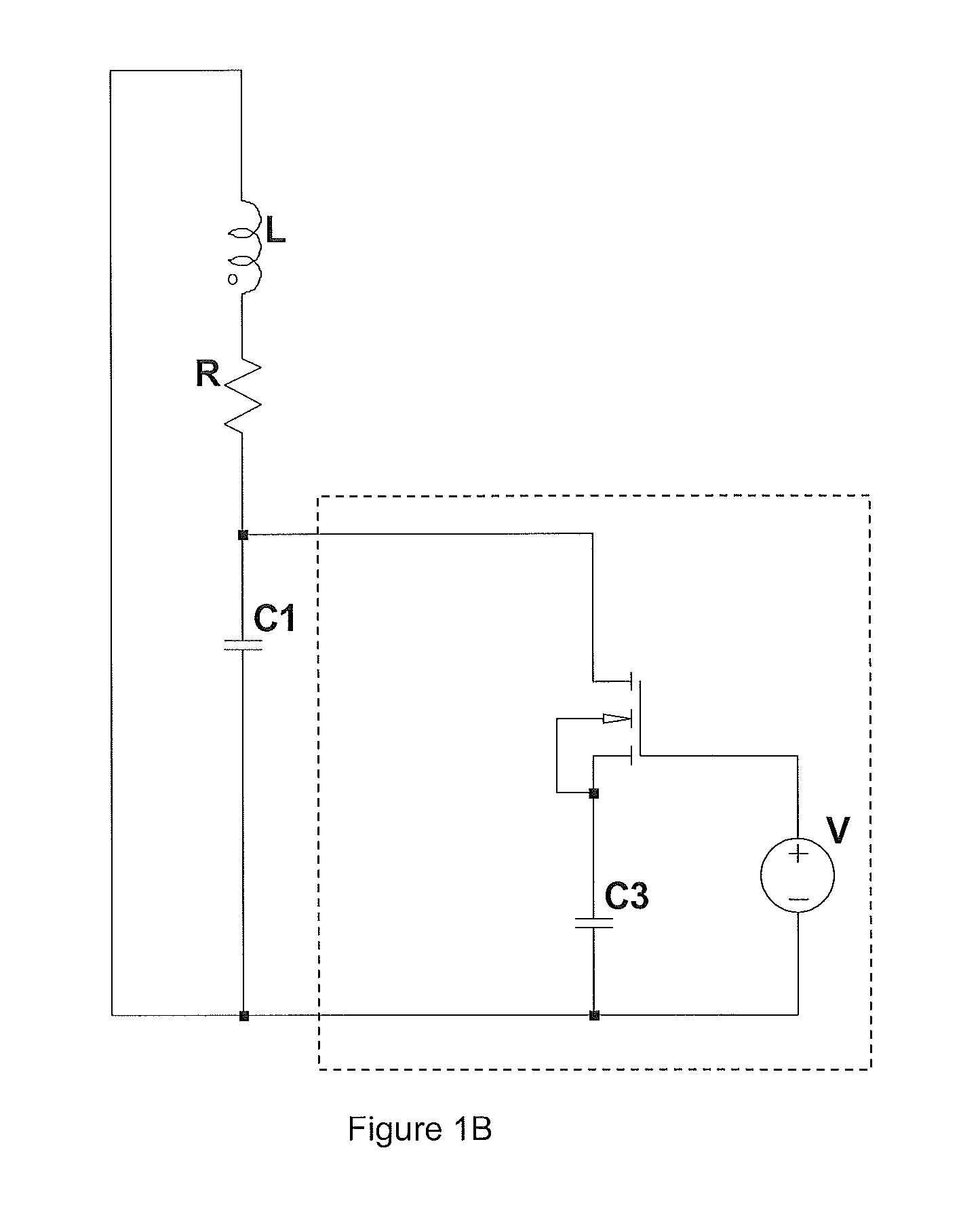
[0085]FIG. 1 shows an embodiment of a self-adaptive resonator. The resonator consists of an antenna L with series resistance R coupled to a capacitive network. The antenna is connected to a capacitive network C1, C2, C3 and a MOSFET. The capacitive network has two distinct states with the MOSFET on and MOSFET off. When the MOSFET is on the total capacitance is C1+C3, since C2 is shorted out, whereas when the MOSFET is off the total capacitance is reduced since C2 and C3 are now in series. The MOSFET is turned on or off depending on the amplitude of the waveform at the source potential, relative to the fixed gate voltage V. The duty cycle of the MOSFET turn on time varies with the resonance amplitude, which naturally adjusts to allow the resonator to match the stimulus frequency.

[0086]The amplitude of the resonator is controlled through the gate voltage V. If the voltage is reduced to negative voltages then the amplitude increases provided the frequency is between the following limit...


PUM


Abstract

A circuit block which comprises a non-linear capacitor with two different values of capacitance dependent on a value of a voltage of a resonant signal on the capacitor; a plurality of second capacitors each coupled to a respective switch to enable a said second capacitor to be switched in or out of parallel connection with the nonlinear capacitor; and a tuning control, coupled to the second capacitor switches, and sensing an amplitude of the resonant signal. The tuning control circuit is configured to control the second capacitor switches to successively switch the second capacitors in/out of parallel connection with the non-linear capacitor dependent on the amplitude of the resonant signal until the non-linear capacitor has substantially a single one of two different values, such that in a resonant circuit the circuit block then behaves as a fixed value capacitor.

Description

FIELD OF THE INVENTION[0001]This invention relates to resonant circuits, and more particularly to circuit blocks and components for resonant circuits and to related tuning methods. Embodiments of the invention are particularly useful in RFID tags.BACKGROUND TO THE INVENTION[0002]Radio frequency identification (RFID) generally employs resonance in order to increase the efficiency of energy transfer from the reader to the tag. This is achieved through the resonant recycling of energy that results in voltage step up in the tag when subject to the reader powering field. The level of step up increases as the Q of the resonant circuit increases and the loss decreases.[0003]However, as the tag Q increases the width of the resonance drops proportionally. High levels of step up, corresponding to high Q, are only achieved over a narrow frequency band. This makes the system susceptible to degradation due to detuning as follows:[0004]1) Environmental detuning can cause the resonant frequency to...

Claims


Application Information

Patent Timeline
Patent Type & Authority Applications(United States)
IPC IPC(8): H03L5/00
CPCG06K19/0701H03J1/0008G06K19/0726G06K19/0723H03J1/00H03J5/246
Inventor HILL, NICHOLAS PATRICK ROLAND
Owner SUREFLAP
Why Eureka
Try Eureka