
Spinal implant device, procedure and system

a technology of spinal implants and fixed devices, applied in the field of medical devices and procedures, can solve the problems of prior art devices not fully blocking the extension of fused vertebrae, deteriorating vertebrae above and below the point of attachment, and limiting flexion, so as to prevent the deterioration of vertebrae and improve the quality of life

Inactive Publication Date: 2009-08-13
BRACKEN SCOTT
View PDF12 Cites 59 Cited by
  • Summary
  • Abstract
  • Description
  • Claims
  • Application Information

AI Technical Summary

Benefits of technology

[0017]It is an object of the invention to improve on the prior art and provide a superior system that prevents the deterioration of vertebrae on either side of a damaged region of the spine that is repaired by having rods fastened on either side of the damaged region.
[0018]It is a further object of the invention to provide a system and procedure that will improve on the quality of life for patients having spinal surgery.

Problems solved by technology

A major problem associated with fusing vertebrae and the prior art is the continued deterioration of vertebrae near the site of the spinal surgery.
Deterioration of vertebra above and below the point of attachment of the prior art devices is believed to be caused by the misapplication of forces onto the point of attachment at the bone screws.
The prior art fails to fully block the extension of the fused vertebrae and limit the flexion of them.
Thus, the vertebrae in and around the affected area continue to experience deterioration.
Thus, the weight of the body is centrally located about the spine and is said to be “centerline loaded.” If forces and loads are experienced on the exterior regions of the vertebrae in an unnatural manner, the vertebrae will deteriorate over time.
Such degeneration will not only deteriorate the vertebra but also the disks between the vertebra and cause pain and injury to the peripheral nerves.
Such forces tend to create a moment of inertia about the bond screws.
If unequal forces are applied to the rods arranged on either side of the spine, then the patient may lean to one side and experience much pain and discomfort.
Over time, activities like walking or setting causes more damage and deterioration to the affected area of the patient's spine.
Thus, patients who have the prior art devices implanted may experience only temporary relief from pain and eventually require the replacement of the prior art device.

Method used


Image

  • Spinal implant device, procedure and system
  • Spinal implant device, procedure and system
  • Spinal implant device, procedure and system

Examples


first embodiment

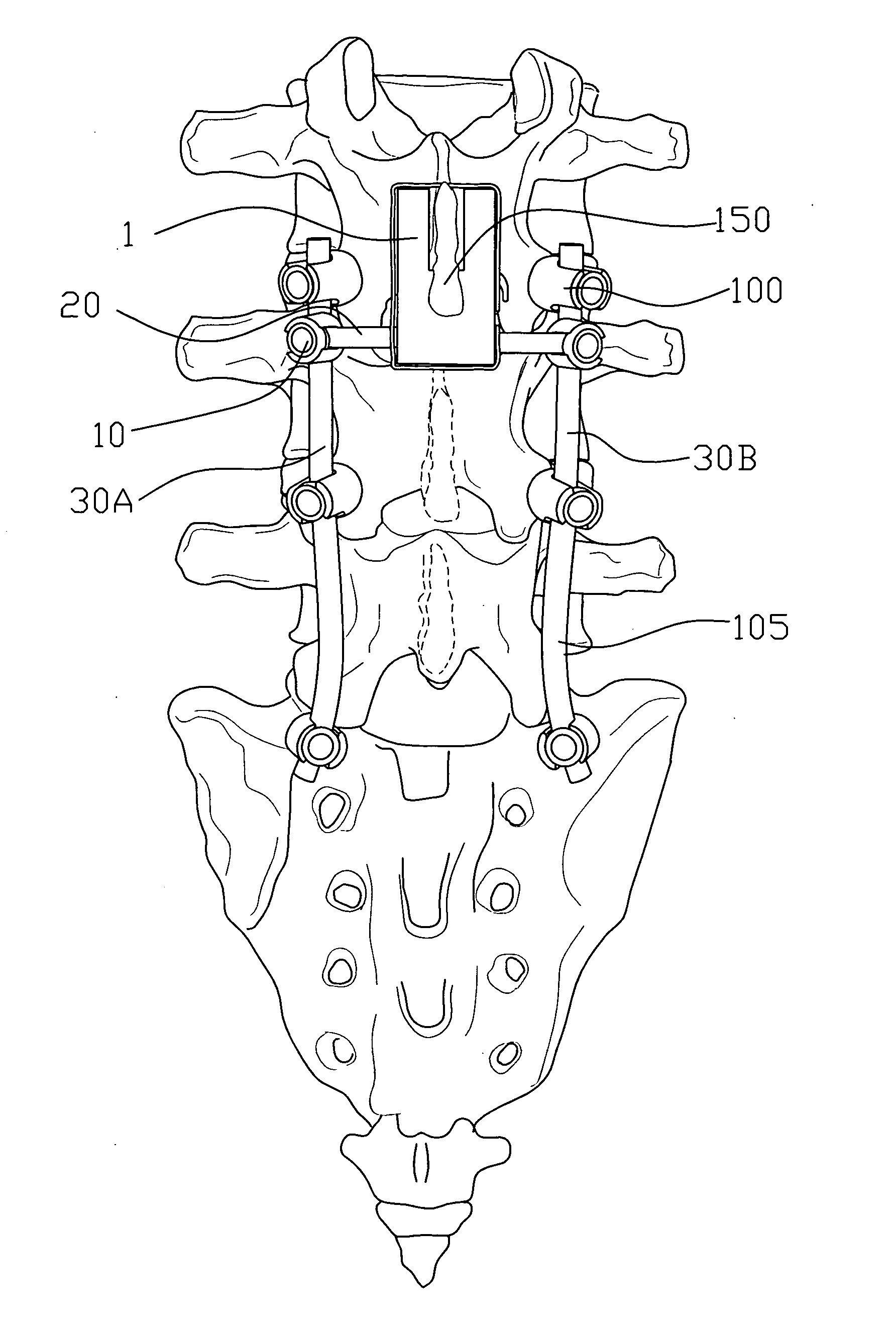
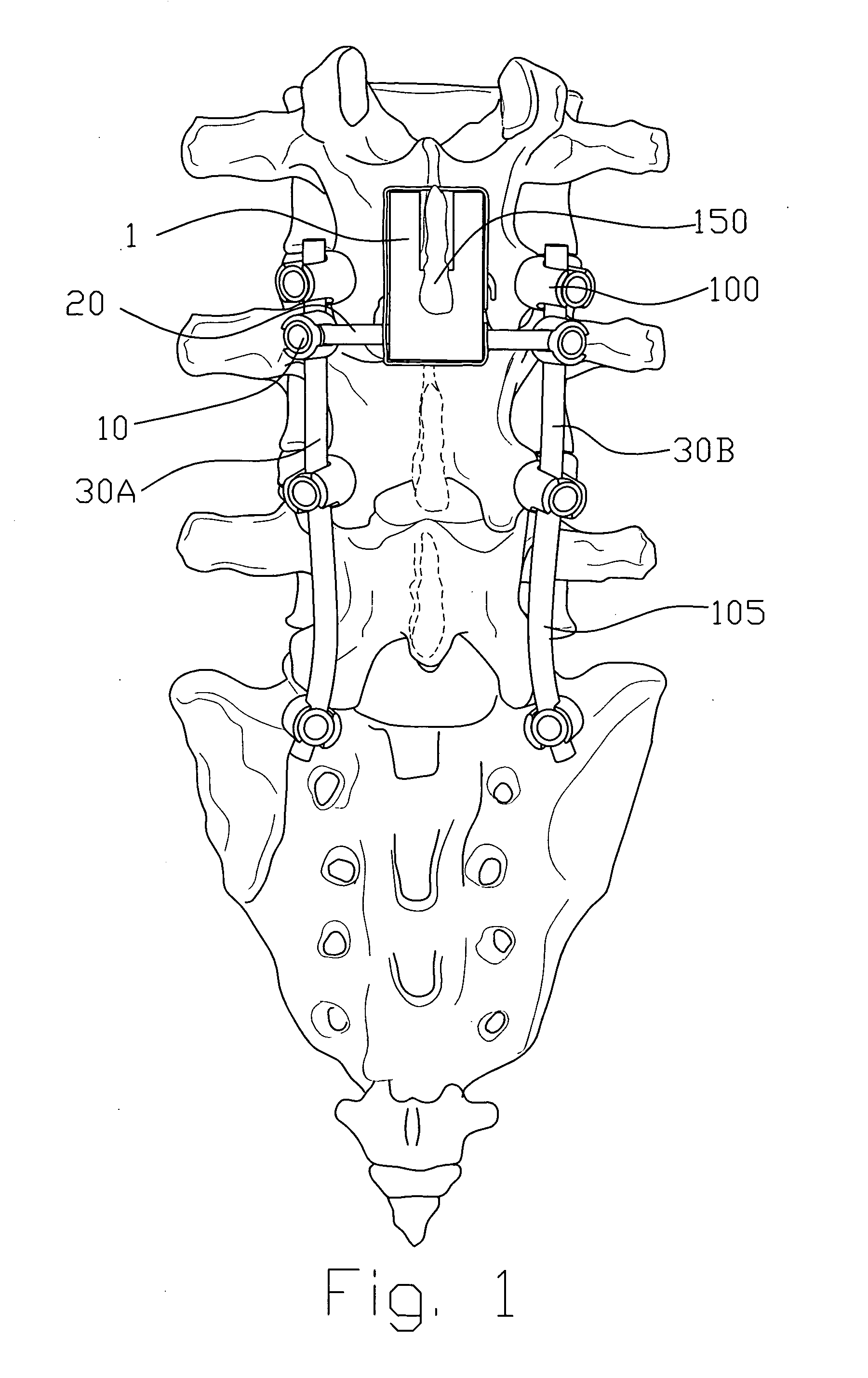
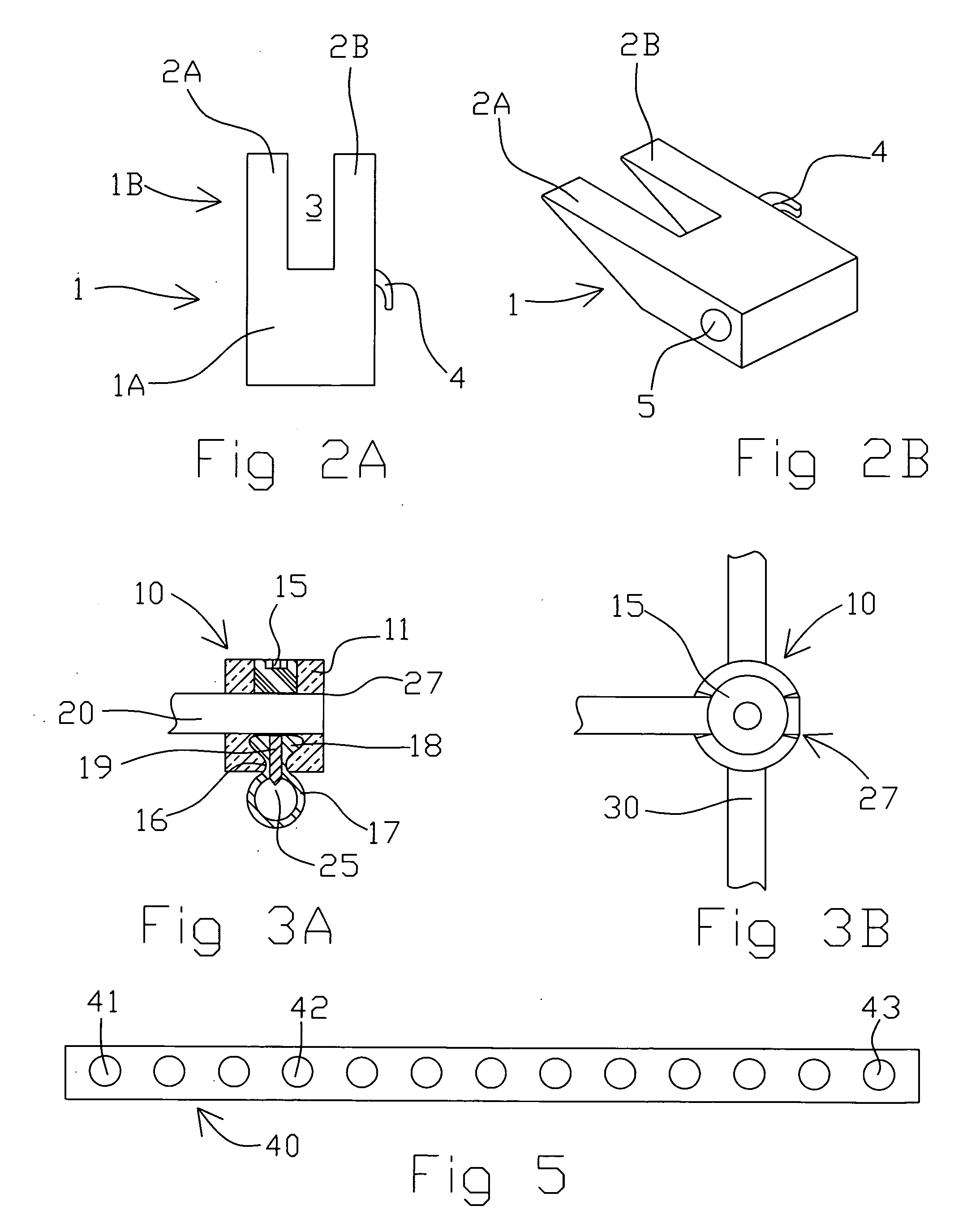
[0031]FIG. 3A shows a cross section view of the cross connector 10. The cross connector 10 includes an orifice 27 that accommodates an end of cross member 20. A pressure exerting device such as setscrew 15 is arranged in the upper center of the cross connector 10 and mates with internal threads within the cross connector 10 to exert pressure onto the cross member 20 to secure it to the cross connector 10. The cross member 20 extends perpendicular to the vertical rods 30A-B, one of which is fastened within the second opening 25 of the cross connector 10. The second opening 25 is defined by a lower ring 17 having an upper end 18 secured within an orifice 16 and secured by a setscrew 19 which forces the upper end 18 outward. Otherwise, either rod 20, 30A-B may be fastened to the cross connector s10 via a tulip end. The tulip end may include a retaining ring, clip, wire or cam for fastening the cross connecctor to the cross member. That is the tulip end is a type of twist fastener that ...

second embodiment

[0032]FIGS. 4A-4C depict the cross connector 10. As can be understood, the cross connector 10 includes a body 11A that comprises threads for accepting setscrew 15. Otherwise, a tulip connector, as shown and disclosed in U.S. Patent Application Publication US 2006 / 0206114 A1 which is incorporated by reference hereto, may be used to exert pressure to hold either the vertical rod or cross member in place. The body 11A is preferably cup-shaped and includes a lower extension 11B that comprises a curved end 11C that accepts on of either the cross member or the vertical rod. A second setscrew 11D preferably secures vertical rod 30 into place as shown.

[0033]FIG. 5 show a strap fastener that includes a plurality of openings therein. The openings are used as discussed above for passing the cross member there through and fastening a second end of the strap fastener to the hook on the side of the block. FIG. 6 shows a bone screw assembly and vertical rod for use with the invention. The vertical...


PUM


Abstract

A spinal implant procedure and system includes vertical rods fastened to the spine on opposite sides. A cross connector is arranged on each vertical rod and to opposite ends of a cross member. The cross member includes a block having a lateral opening and that includes a forked end that is arranged at a bottom side of a spineous process. A strap fastener include openings through which the cross member passes. An opening of the strap fastener hooks on a catch on the side of the block. The block limits prevents rotation, blocks extension and limits flexion of the affected vertebrae.

Description

[0001]The present application relates to and claims priority from U.S. Provisional Application Ser. No. 61 / 063,975 filed on Feb. 7, 2008.[0002]The present application was not subject to federal research and / or development funding.TECHNICAL FIELD [0003]The invention generally relates to medical devices and procedures used in some spinal surgeries to immobilize certain vertebrae of the spine. More particularly, the invention relates to an improved medical procedure and spinal fixation system for use in medical procedures performed during spinal surgery. The surgical device is a block that couples to a spineous process to immobilize an injured region of the spine. A pair of fixed rods are affixed in bone screws and arranged on opposite sides of a spine. A cross member is arranged between the fixed rods and passes through the block that includes a notch. A strap, having a plurality of openings arranged therein, is wrapped about the block to secure it to the spineous process. The cross m...

Claims


Application Information

Patent Timeline
Patent Type & Authority Applications(United States)
IPC IPC(8): A61B17/70
CPCA61B17/7037A61B17/7067A61B17/7049
Inventor BRACKEN, SCOTT
Owner BRACKEN SCOTT
Features
  • Generate Ideas
  • Intellectual Property
  • Life Sciences
  • Materials
  • Tech Scout
  • Unparalleled Data Quality
  • Higher Quality Content
  • 60% Fewer Hallucinations
Learn More