Knee joint with a ramp

a technology of ramps and knee joints, applied in knee joints, prostheses, medical science, etc., can solve the problems of reducing affecting the service life of the knee joint, so as to reduce the wear and deformation of the polyethylene surface.

Inactive Publication Date: 2009-08-13
NEW YORK UNIV
View PDF61 Cites 62 Cited by
  • Summary
  • Abstract
  • Description
  • Claims
  • Application Information

AI Technical Summary

Benefits of technology

[0009]When the system is used as a CR device, the PCL provides some of the motion guidance. When used as a PS device, the features of the ramp guide the motion. Sufficient laxity about the neutral path allows for variations of motion. One of the benefits of the system is that anterior sliding of the femur on the tibia from approximately 0-60° flexion (paradoxical motion) is minimized due to the medial femoral recess as it interfaces with the antero-medial tibial pad feature.
[0011]Large contact surface areas between the femoral and tibial components, especially on the medial side, which is highly loaded than the lateral side, minimize wear and deformation of the polyethylene surfaces. Additionally, smooth contours around the central tibial ramp avoid stress concentrations which could result in damage to the plastic. Minimal bone resection is required from the central part of the femur for installation of the femoral component.

Problems solved by technology

Due to variations in surgical techniques and between patients, when using the CR type of total knee, it has been difficult to obtain an optimal tightness of the posterior cruciate ligament (PCL) throughout flexion, resulting in variable rollback patterns.
Damage can sometimes occur to the plastic post in the long term, anteriorly due to impacts at full extension, and posteriorly due to high flexion loading.
In addition, in many PS designs, there is a tendency for overconstraint in rotation due to the dishing of the tibial bearing surfaces, in combination with the construct of the cam-post.
A disadvantage common to both CR and PS types, although more pronounced with CR designs due to their shallower tibial bearing surfaces, is a paradoxical motion in which the femur slides forwards on the tibial surface during the first half of the flexion range, rather than backwards which is the required motion.
Also, uneven or jerky motion occurs in many cases.
However, these configurations may not incorporate a mechanism for achieving lateral rollback in flexion in combination with a relatively immobile medial side, or do not provide sufficient laxity about the neutral path of motion.

Method used


Image

  • Knee joint with a ramp
  • Knee joint with a ramp
  • Knee joint with a ramp

Examples


Embodiment Construction

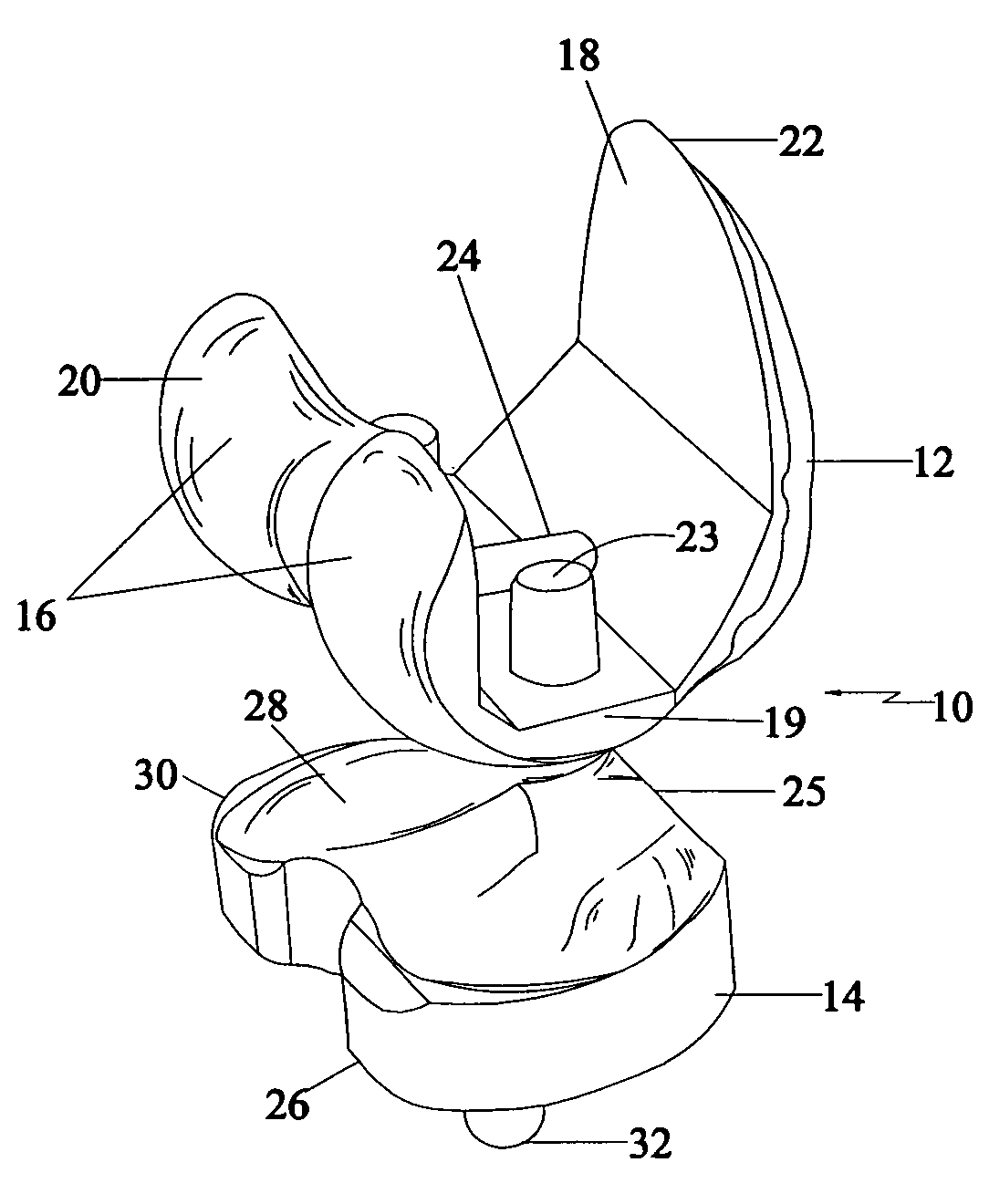
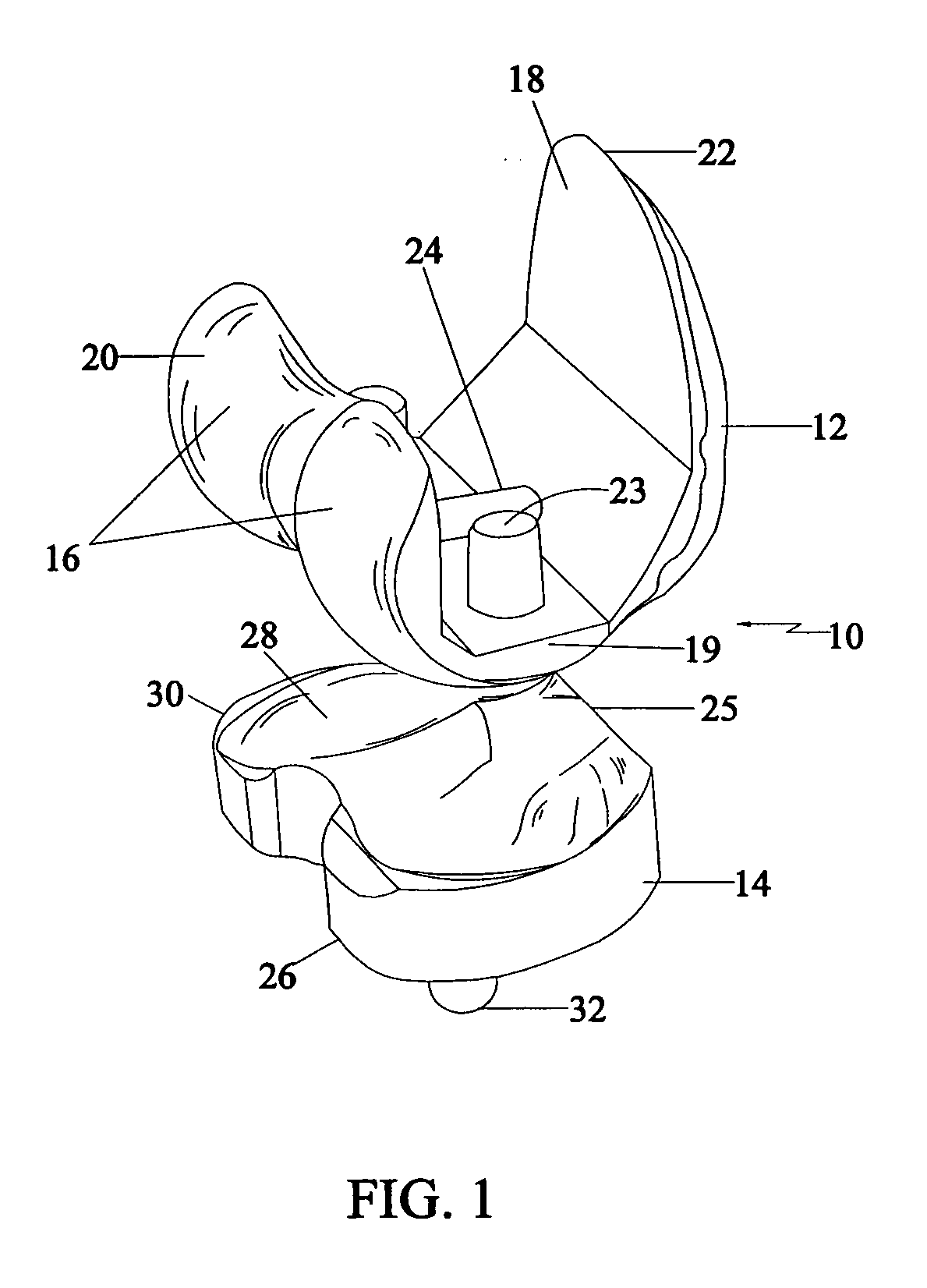
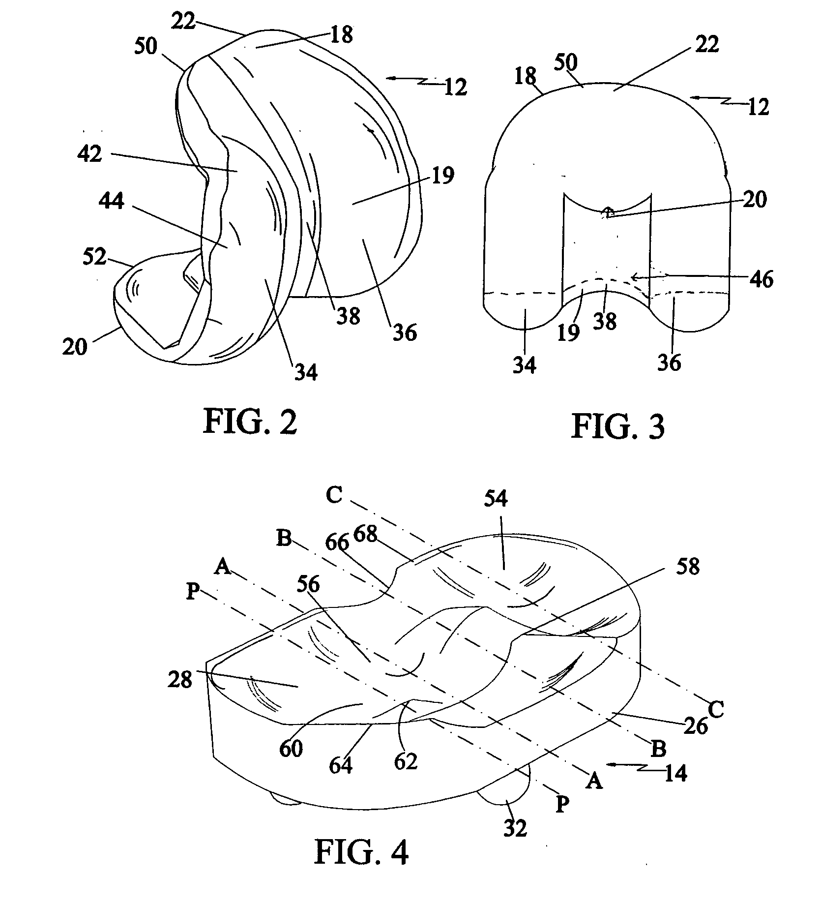
[0027]Referring to FIG. 1, the knee joint 10 in a zero degree flexion in accordance with a preferred embodiment of the present invention is shown. The knee joint 10 of the present invention includes a femoral component 12 and a tibial component 14. Femoral component 12 is preferably connected to a predefined distal end of a femur. The tibial component 14 is preferably connected to a predefined proximal end of a tibia.

[0028]The femoral component 12 is a one-piece arcuate construction that includes a pair of convex femoral condyles 16 and a patella flange 18. Condyles 16 and patella flange 18 converge inwardly to meet in the distal portion 19 of the femoral component 12 to form the arcuate shape. The pair of condyles 16 forms a proximal-posterior portion 20 and the patella flange 18 forms an opposed proximal-anterior portion 22. An interior side of distal portion 19 has a pair of pegs 23. The interior side of the distal portion 19 of femoral component 12 includes approximately central...


PUM


Abstract

An artificial knee joint is described that includes a femoral component with a specially shaped bearing surface and a tibial component, whose surface interacts with the femoral surfaces. The interaction provides for the required motion and stability characteristics. The interaction between the femoral and tibial surfaces is such that as the knee is flexed to maximum, the femoral component moves posteriorly on the tibial surface, by an amount similar to that in the anatomic knee. The opposite motion, roll forward of the femur from a fully flexed to a more extended position, is accomplished by varying the outward radii of the lateral and medial femoral bearing surfaces, together with a ramp on the postero-lateral and postero-medial regions of the tibial surfaces.

Description

FIELD OF THE INVENTION[0001]The present invention relates to total knee prostheses and more specifically to a knee joint having femoral components and a tibial component that are specifically shaped for posterior cruciate retention and substituting.BACKGROUND OF THE INVENTION[0002]The large majority of the total knees implanted today are either of the posterior cruciate retaining (CR) or posterior stabilized (PS) types. These have both functioned well clinically, but a number of disadvantages remain. Due to variations in surgical techniques and between patients, when using the CR type of total knee, it has been difficult to obtain an optimal tightness of the posterior cruciate ligament (PCL) throughout flexion, resulting in variable rollback patterns.[0003]For the PS, considerably extra bone needs to be resected from the center of the femur to accommodate the intercondylar housing of the femoral component, for the cam and post mechanism. Damage can sometimes occur to the plastic pos...

Claims


Application Information

Patent Timeline
Patent Type & Authority Applications(United States)
IPC IPC(8): A61F2/38A61F2/30
CPCA61F2/3886A61F2230/0006A61F2002/30878A61F2002/30116
Inventor WALKER, PETER STANLEY
Owner NEW YORK UNIV
Why Eureka
Try Eureka