

Control valve for a variable capacity compressor
a variable capacity compressor and control valve technology, which is applied in the direction of positive displacement liquid engines, lighting and heating apparatus, soldering apparatus, etc., can solve the problems of increasing the manufacturing cost of electromagnetic control valves, heat treatment, and assembly bodies that have been once subjected to brazing process. , to achieve the effect of low cos
Image

Examples
first embodiment
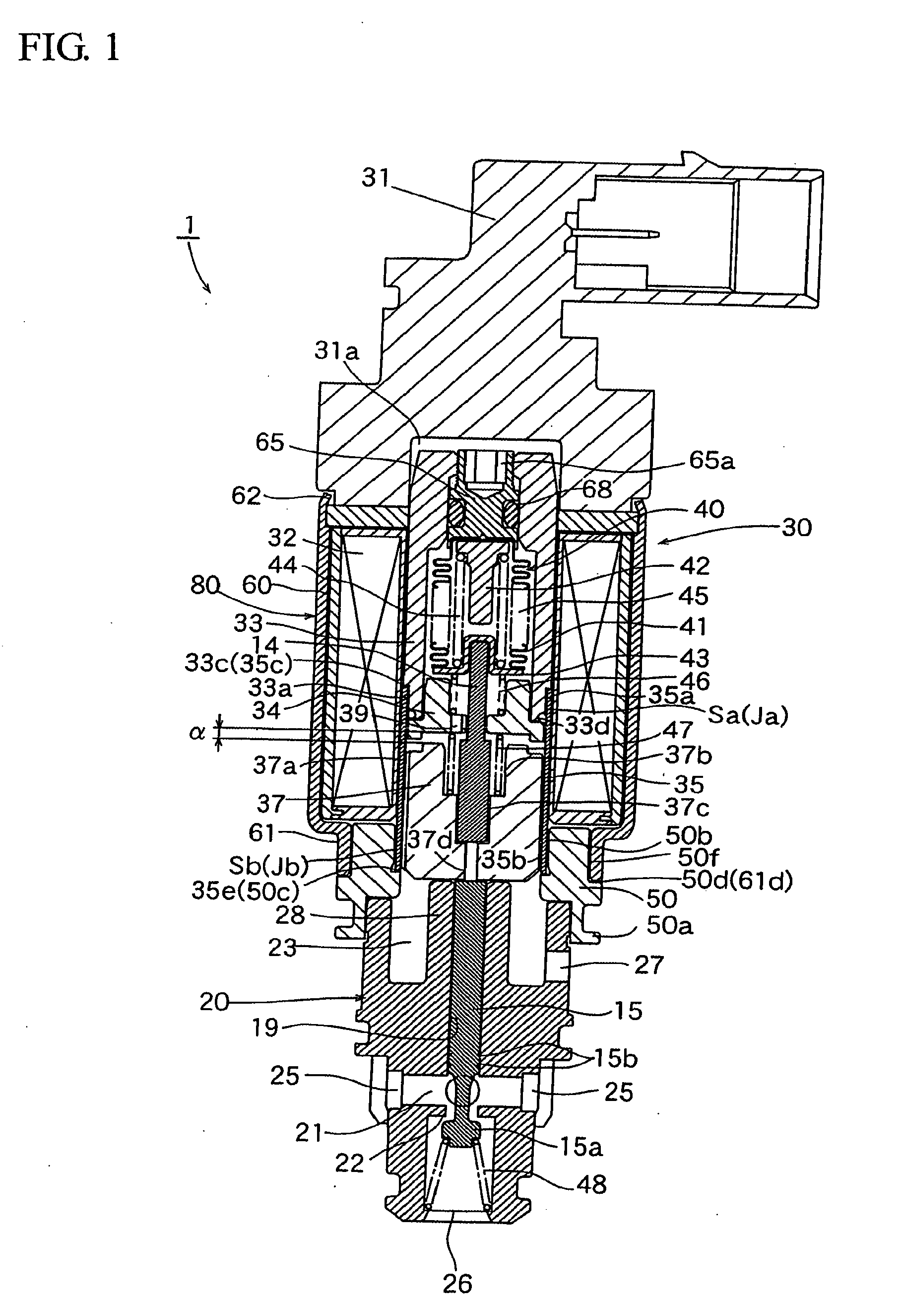
[0051]FIG. 1 shows a longitudinal sectional view illustrating one embodiment of the electromagnetic control valve for a variable capacity compressor, that has been manufactured according to the brazing method and manufacturing method representing one embodiment according to the present invention. In the following description, the construction of the electromagnetic control valve 1 will be explained at first, and then the method of manufacturing the electromagnetic control valve 1 will be explained.
[0052]The control valve 1 shown in FIG. 1 is equipped with a valve rod 15 having a valve body 1a; a valve main body 20 composed of a valve chamber 21 provided with a valve seat (valve aperture) 22 with which the valve body 1a can be retractivebly contacted, a plurality of inlet ports 25 for introducing a cooling medium of discharge pressure “Pd” from the compressor into the outer peripheral portion of the valve chamber 21 (on the upstream side of the valve seat 22), and a high pressure coo...
second embodiment
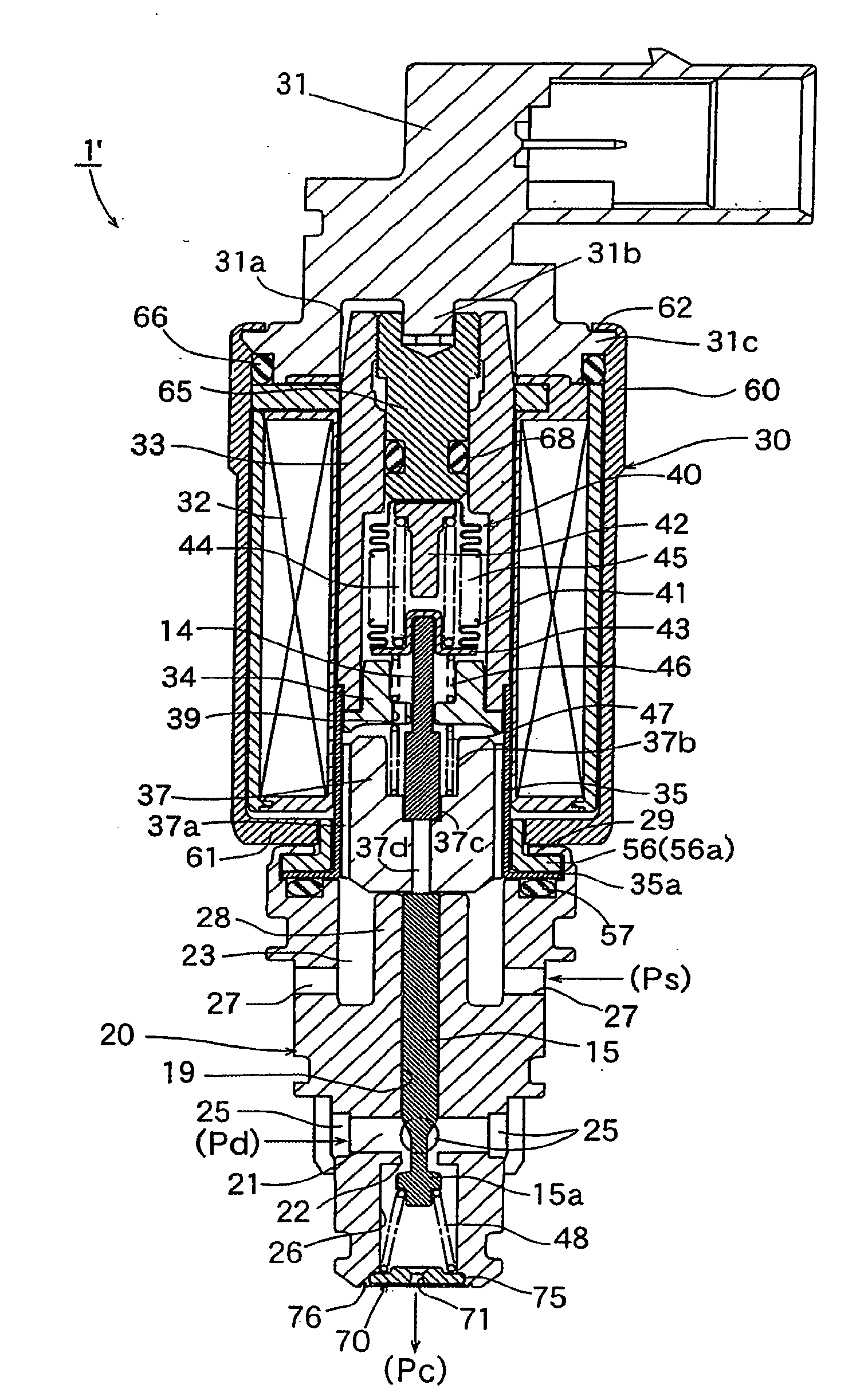
[0072]FIG. 6 is a longitudinal sectional view illustrating a second embodiment of the control valve for a variable capacity type (crutch-attached) compressor according to the present invention.
[0073]The control valve 1′ for crutch-attached compressor shown in FIG. 6 is constructed such that a restricting mechanism (throttle aperture-attached closing member 70) to be described hereinafter is attached to a control valve for a crutch-less compressor. In other words, all of the components other than the restricting mechanism are the same as those of the crutch-less compressor. Next, the construction of the control valve 1′ will be explained in detail as follows.
[0074]The control valve 1′ comprises: a valve rod 15 having a valve body 15a having a +-shaped or T-shaped cross-section and attached to a lower end of the valve rod 15; a valve main body 20 provided with a valve chamber 21 having a valve aperture (valve seat) 22 with which the valve body 15a can be retractivebly contacted, with ...
third embodiment
[0086]Next, a third embodiment of the control valve for a variable capacity type (crutch-attached) compressor according to the present invention will be explained.
[0087]The control valve 1″ according to this embodiment is the same in fundamental structure as that of the control valve 1′ of the second embodiment shown in FIG. 6 except that the magnitude of opening of valve (the magnitude of lift “L” from the valve aperture 22 of the valve body 15a (see FIG. 7)) is regulated in order to suppress the change in gradient of controlling pressure (see FIG. 8) that may be caused due to the provision of the throttle aperture-attached closing member 70 as a restricting mechanism.
[0088]Next, the construction of the control valve 1″ will be explained in detail as follows.
[0089]Due to the provision of the throttle aperture-attached closing member 70 as a restricting mechanism, when the value of electric current to be fed to the coil 32 becomes smaller than “Ia” which is close to zero (for exampl...
PUM
| Property | Measurement | Unit |
|---|---|---|
| melting temperature | aaaaa | aaaaa |
| melting temperature | aaaaa | aaaaa |
| electric current | aaaaa | aaaaa |
Abstract
Description
Claims
Application Information
- IPC
- F04B49/02; F16K31/02; F04B49/03
- CPC
- B23K1/0008; B23K35/30; F04B27/1804; C21D1/68; C21D6/00; B23K2203/04; B23K2103/05; B23K1/19
- Inventors
- KUME, YOSHIYUKI; IMAI, MASAYUKI