Reversibly attachable shade for mobility aids

a technology of mobility aids and shade, which is applied in the field of reversible attachable shade for mobility aids, can solve the problems of difficult for many users to maintain their balance, difficult for elderly and infirm people, and almost always use both hands, and achieves the effects of convenient attachment, removal, handling and storag

Inactive Publication Date: 2009-08-20
SAPP PAUL
View PDF13 Cites 9 Cited by
  • Summary
  • Abstract
  • Description
  • Claims
  • Application Information

AI Technical Summary

Benefits of technology

[0025]In one embodiment of the invention the upper components including the joint and shade can be reversibly removed from the shaft. If the shaft is of the telescoping type, the entire device can be reduced to a size that permits easy attachment, removal, handling, and storage.

Problems solved by technology

One common problem encountered by the users of mobility aids is that one must almost always use of both hands to operate a mobility aid.
For instance, it is difficult, and in some cases impossible, for the elderly and infirm to guide a rolling walker with one hand, and it is even more difficult for many users to maintain their balance when holding onto a rolling walker with just one hand.
Consequently, when the user of a mobility aid needs to deploy an overhead shade, such as an umbrella or sun-shade, it can be quite difficult, and in many instances impossible or dangerous, for the person to remove their had from the mobility aid to hold the shade over their head.
Consequently, those who are dependent on mobility aids are often forced to avoid going out of doors when the weather is inclement or is predicted to be inclement; consequently, the quality of their lives is compromised.

Method used


Image

  • Reversibly attachable shade for mobility aids
  • Reversibly attachable shade for mobility aids
  • Reversibly attachable shade for mobility aids

Examples


Embodiment Construction

1. Basic Preferred Embodiment of the Invention

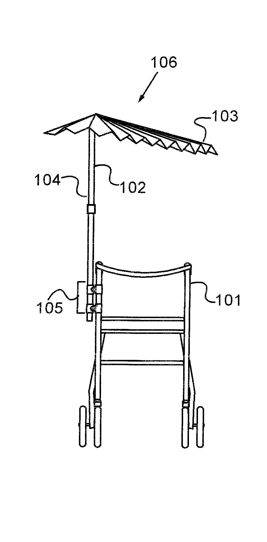
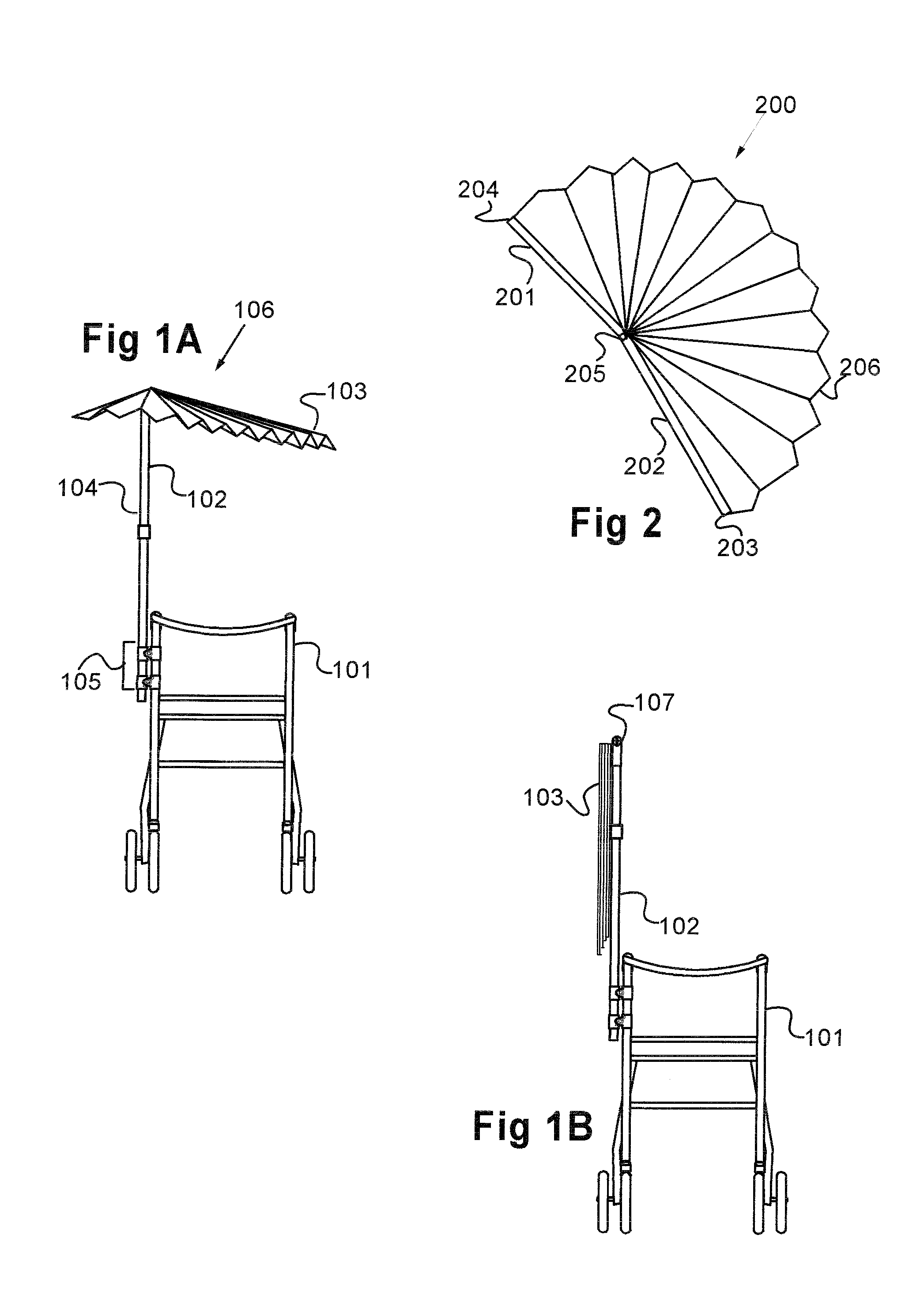
[0035]Referring first to FIG. 1A, an attachable overhead shade device 106 is shown attached to a mobility aid such as a rolling walker 101. The device comprises a shaft 102 combined with a shade 103.

[0036]The lower end of the shaft is reversibly attached to the walker by connector 105, which holds the shaft in a functionally vertical orientation. Shade 103 is connected to the upper end of the shaft. In FIG. 1A the invention is shown in a deployed configuration, which is to say the shade is raised into a functionally horizontal orientation and opened over the user's head, thereby providing shade and protection to the user from the elements such as sun and rain.

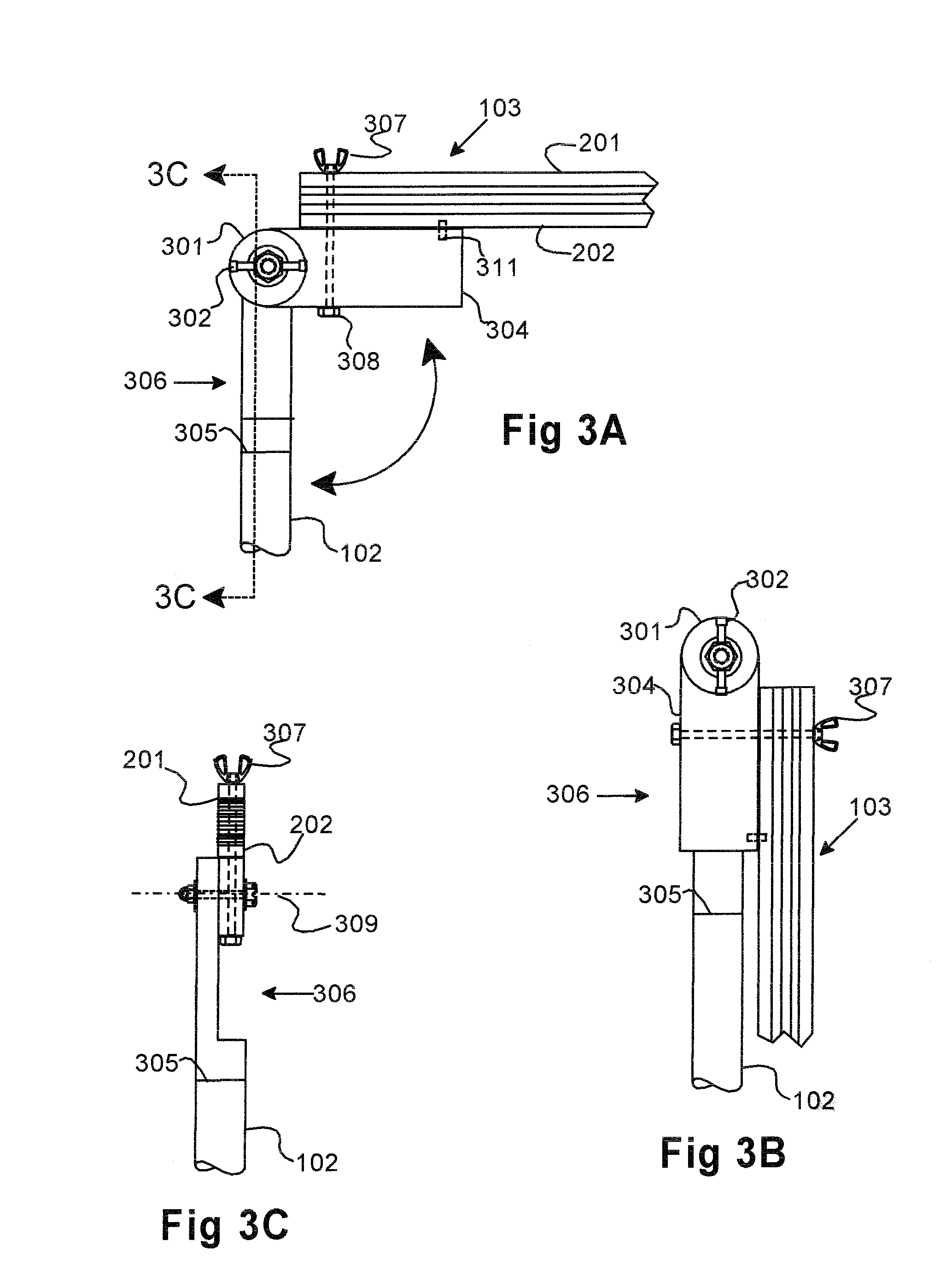
[0037]FIG. 1B depicts the invention in a non-deployed configuration in which shade 103 is closed and rotated approximately 90 degrees from the deployed configuration so that it is oriented functionally vertically and is substantially parallel to and juxtaposed against shaft 102.

[003...


PUM


Abstract

The invention comprises an overhead shade device adapted to be attached to a mobility aid. The invention has an elongate shaft having an upper end and a lower end. The shaft is attached to the mobility aid at the shaft's lower end in a manner that holds the shaft functionally vertically. A shade is attached to the upper end of the shaft. The shade may be an umbrella-type shade, or a fan, or other functionally horizontal surface that shades the user when deployed.In one embodiment of the invention, the perimeter of the shade when opened includes a base side and an arc of less than 360 degrees, and more preferably, an arc of less than about 200 degrees. The base side does not extend significantly beyond the outer edge of one side of the user and / or mobility aid when said shaft is held in a functionally vertical orientation. The area of the shade may be continuously variable between its limits.

Description

BACKGROUND OF THE INVENTION[0001]1. Field of the Invention[0002]The invention relates to attachable shades, particularly shades that can be attached to walkers and similar mobility aids.[0003]The following lexicon sets forth the intended scope and meaning of certain terms and concepts used in the specification and claims. The examples provided in this lexicon are intended to clarify and not to limit the meaning of the respective terms. If not otherwise indicated, the definitions set forth here apply to the plural and all grammatical variations of the terms defined.[0004]A / AN / THE—unless otherwise indicated, the articles “a” and “an” include the plural. The article “the” when used to refer to a noun introduced with “a” or “an” also includes the plural.[0005]MOBILITY AID—a device that enhances the personal mobility of a user. Mobility aids include, by way of example, walkers of all types, wheel chairs, electric scooters, prams, motorized carts, and personal transport devices such as de...

Claims


Application Information

Patent Timeline
Patent Type & Authority Applications(United States)
IPC IPC(8): A45B17/00
CPCA45B11/00A45B23/00A45B19/00A45B2023/0087
Inventor SAPP, PAUL
Owner SAPP PAUL
Why Eureka
Try Eureka