
Motor unit

a technology of motor units and motors, applied in the direction of dynamo-electric machines, electrical equipment, supports/enclosements/casings, etc., can solve the problems of burrs on the mounting plate, impairing the accuracy of driving performance of driving objects, etc., and achieve the effect of high accuracy

Inactive Publication Date: 2009-08-20
SANKYO SEIKI MFG CO LTD
View PDF2 Cites 2 Cited by
  • Summary
  • Abstract
  • Description
  • Claims
  • Application Information

AI Technical Summary

Benefits of technology

[0006]In view of the problems described above, at least an embodiment of the present invention may provide a motor unit that suppresses a tilt of the motor unit itself due to the burrs and enhances the accuracy of driving performance of the driving device.
[0009]In the motor unit according to at least an embodiment of the present invention, the edge of the connecting section of the base plate of the mounting plate is cut out or ground, the connecting section being for connection to the motor-driven device. Eventually, burrs at the edge caused at the time of cutting the mounting plate are Removed. Therefore, the motor unit is installed without any tilt with respect to the motor-driven device due to the burrs caused in the connecting section, and the driving object can be driven with high accuracy.
[0011]According to this disposition, the motor unit can be fixed to the motor-driven device without any tilt with respect to the motor driven device even though the mounting plate is U-shaped in its cross section having the turning shaft support to support the top end of the turning shaft. Therefore, the driving object can be driven with high accuracy.
[0013]Thus, when the motor unit is installed by using each one side surface of the base plate and either of the stator support and the turning shaft support as the connecting section for connection to the motor-driven device, and namely the motor unit is installed, being laid horizontally; the installation space of the motor unit can be reduced in a vertical direction. For this disposition, if used as a connecting section for connection to the motor-driven device are not only the side surface of the base plate but also either or both of the side surface of the stator support and the turning shaft support, the connecting section becomes either L-shaped or U-shaped so that the motor unit can be installed further stably. Furthermore, all the side surfaces such as the side surface of the base plate, which work as the connecting section, are cut out or ground, and therefore the motor unit is installed without any tilt due to the burrs caused by cutting.
[0015]When the side surface of the base plate has the protrusions protruding in the horizontal direction of the base plate, not all the side surface of the base plate but only the protrusions need to be cut out or ground. According to this disposition, the motor unit can be fixed to the motor-driven device without any tilt in the same way as described above. Furthermore, the area to be cut out or ground in the mounting plate becomes limited and this leads to a reduction in the production cost of the motor unit Preferably, the manufacturing process of cutting out or grinding the edge of the connecting section should be so carried out as to have a flat area left on the connecting section.
[0017]In the case of a motor unit according to at least an embodiment of the present invention, the cutting or grinding operation, carried out for the edge of the connecting section of the mounting plate to connect with the motor-driven device, removes the burrs of the connecting section, which came up at the time of the cut working of the mounting plate. Therefore, the motor unit has no chance to be installed with any tilt due to the burrs of the mounting plate, and the driving object can be driven with high accuracy.

Problems solved by technology

Unfortunately this mounting plate has burrs at a sheared section, since the mounting plate is made by press working of a metal plate.
Therefore, the burrs make the motor unit installed have a tilt to the motor driven device and / or it impairs the accuracy of driving performance of a driving object connected to a carriage.

Method used


Image

  • Motor unit
  • Motor unit
  • Motor unit

Examples


first embodiment

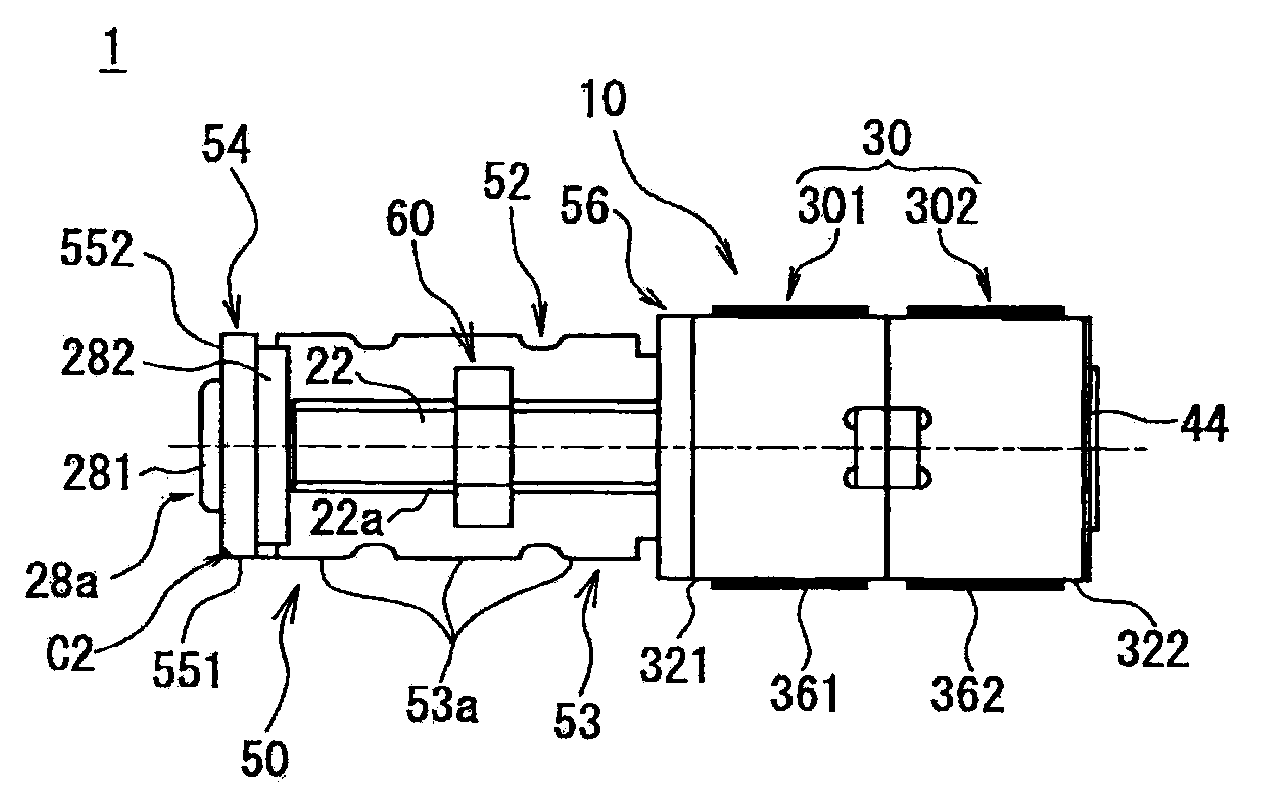
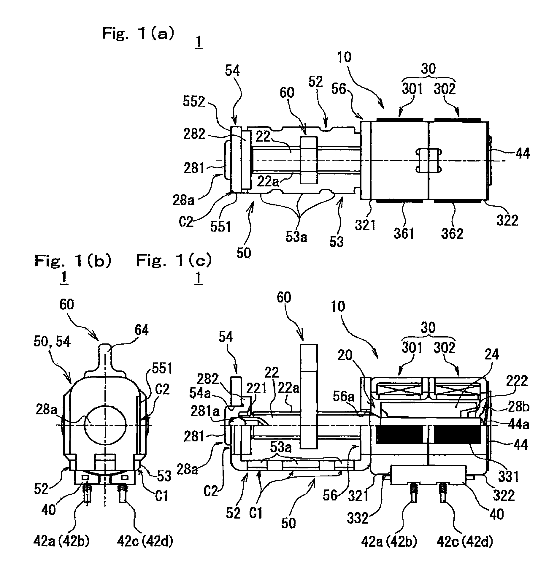
[0047]FIG. 3A shows a condition where a motor unit la according to a first embodiment is mounted on a motor-driven device. FIG. 3B is a cross-sectional view taken from the line A-A in FIG. 3A. As FIGS. 3A and 3B show, the motor unit 1a is fixed by connecting the side surface 53 of the base plate 52 to a mounting surface 101 of a motor mounting section 100 in the motor-driven device. In other words, the side surface 53 of the base plate 52 is a connecting section.

[0048]In the present embodiment, the three protrusions 53a in the side surface 53 of the base plate 52, which work as a section for connection with the motor-driven device, are chamfered to have a chamfer C1 as described above so that burrs caused by press-working (cutting) at the protrusions 53a are removed. Therefore, even if the motor unit 1a is horizontally mounted onto the mounting surface 101 of the motor mounting section 100 in the motor-driven device, i.e., by using the side surface 53 of the base plate 52 as a conne...

second embodiment

[0054]In the first embodiment shown in FIGS. 3A and 3B, the side surface 53 of the base plate 52 and the side surface 551 of the turning shaft support 54 work as sections for connection with the motor-driven device. Alternatively, as shown in FIG. 4A, a motor unit 1b may be so constructed as to use a side surface 57 of the stator support 56 (a lower side surface in FIG. 4A) in addition to the side surface 53 of the base plate 52 for connection with the motor-driven device. According to this arrangement, the section for connecting the motor unit 1b to the mounting surface 101 of the motor mounting section 100 in the motor-driven device becomes L-shaped in the same manner as described for the first embodiment so that the motor unit 1b can stably be fixed. In this case, for avoiding any tilt of the motor unit 1b being installed, it is required to chamfer an opposite side edge to the output side in the side surface 57 of the stator support 56 (an edge side line at the opposite side to t...

third embodiment

[0055]In the first and second embodiments, a combination of the side surface 53 of the base plate 52 and the side surface 551 of the turning shaft support 54, or another combination of the side surface 53 of the base plate 52 and the side surface 57 of the stator support 56 works as a section for connection with the motor-driven device, while the connecting section being L-shaped. Alternatively, as shown in FIG. 4B, a motor unit 1c may be so constructed as to use all the side surface 53 of the base plate 52, the side surface 551 of the turning shaft support 54, and the side surface 57 of the stator support 56 for connection with the motor-driven device. According to this arrangement, the section for connecting the motor unit 1c to the mounting surface 101 of the motor mounting section 100 in the motor-driven device becomes U-shaped so that the motor unit 1c can furthermore stably be fixed. It is required to carry out cutting out or grinding each corresponding edge of the side surfac...


PUM


Abstract

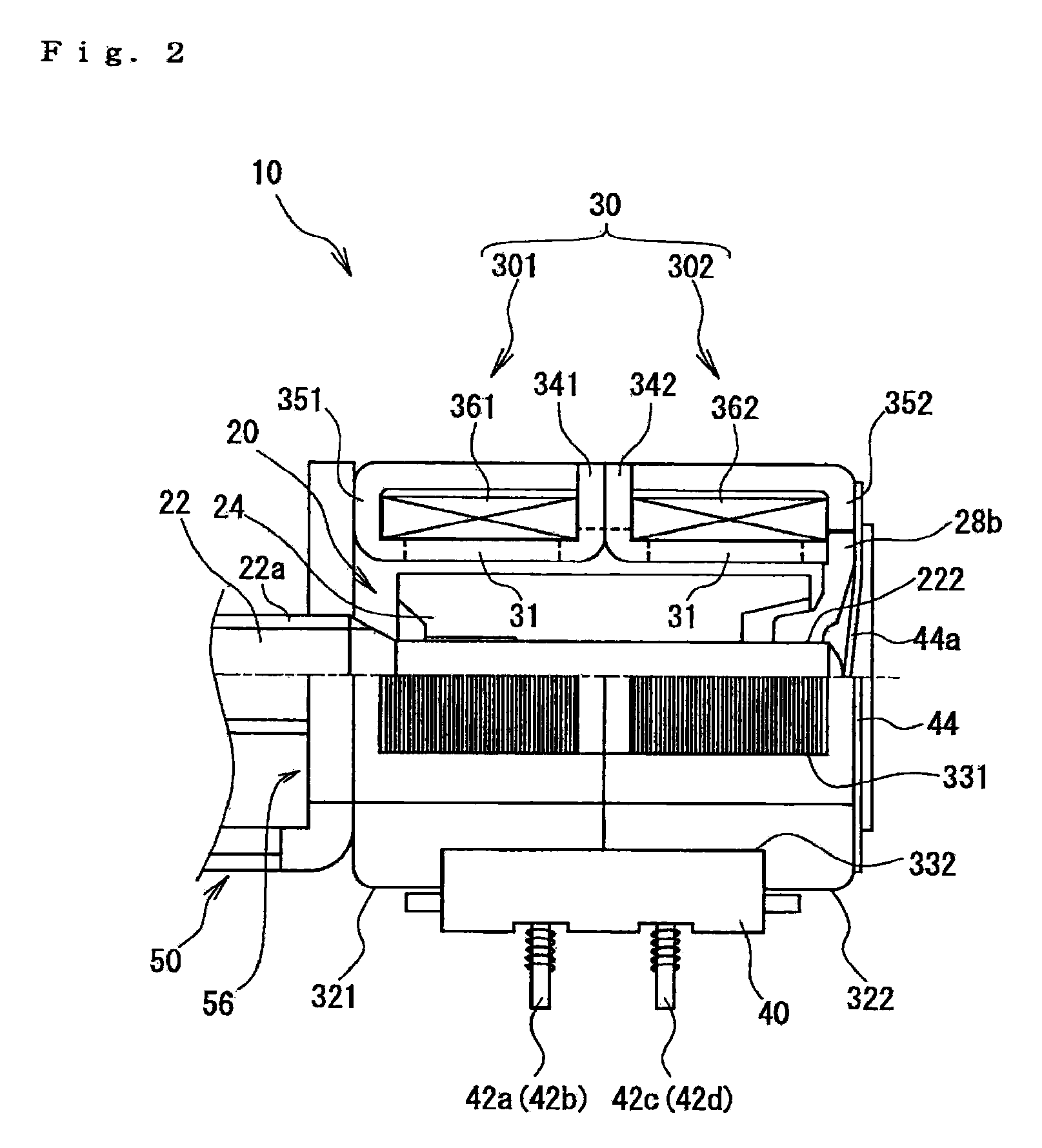
A motor unit for use with a motor-driven device may include a motor main body, having a stator and a turning shaft protruding from the stator; and a mounting plate for installing the motor main body on the motor driven device to which driving power of the motor main body is transmitted. The mounting plate may be structured by cutting a metal plate, and the mounting plate may include a tabular base plate and a stator support The tabular base plate may have a connecting section for connection to the motor-driven device, and the stator support rises from the tabular base plate and may be fixed to the stator. An edge of the connecting section may be chamfered shaped

Description

CROSS REFERENCE TO RELATED APPLICATION[0001]The present invention claims priority under 35 U.S.C. § 119 to Japanese Application No. 2008-28347 filed Feb. 8, 2008, the entire contents of which are incorporated herein by reference.FIELD OF THE INVENTION [0002]The present invention relates to motor units, and more particularly to a motor unit including a mounting plate to fix a motor main body onto a motor-driven device using the motor as a driving unit.[0003]Conventionally known is a motor unit to be mounted on a motor-driven device (such as an optical head device having an optical lens) using the motor as a driving unit This kind of motor unit includes a metal mounting plate with which the motor main body is fixed to the motor-driven device (For example, refer to Patent Document 1). As FIG. 2B of Patent Document 1 shows, the motor unit of this type is installed generally by connecting a base part of the mounting plate to a chassis of the motor driven device or equivalent.[Patent Docu...

Claims


Application Information

Patent Timeline
IPC IPC(8): H02K5/00
CPCH02K5/04H02K37/14H02K7/06H02K5/00H02K7/00H02K37/02
Inventor SONOHARA, HIROYUKI
Owner SANKYO SEIKI MFG CO LTD
Learn More