Failure detection apparatus for resolver

a detection apparatus and resolver technology, applied in the direction of motor/generator/converter stopper, dynamo-electric converter control, instruments, etc., can solve the problem that the resolver operating in the normal state cannot be detected and the actual failure of the resolver cannot be determined, so as to achieve accurate detection.

Inactive Publication Date: 2009-08-20
HITACHI ASTEMO LTD
View PDF4 Cites 33 Cited by
  • Summary
  • Abstract
  • Description
  • Claims
  • Application Information

AI Technical Summary

Benefits of technology

[0004]Therefore, it is an object of the present invention to provide a failure detection apparatus for a resolver, which is capable of accurately detecting (deciding) a failure of the resolver.

Problems solved by technology

In this case, since the state where the value of sin2 θ+cos2 θ is outside the normal range does not continue, there is a fear that the actual failure of the resolver cannot be detected.
In this case, there is a fear that the resolver actually operating in the normal state is regarded (decided) as in the failure state.

Method used


Image

  • Failure detection apparatus for resolver
  • Failure detection apparatus for resolver
  • Failure detection apparatus for resolver

Examples


first embodiment

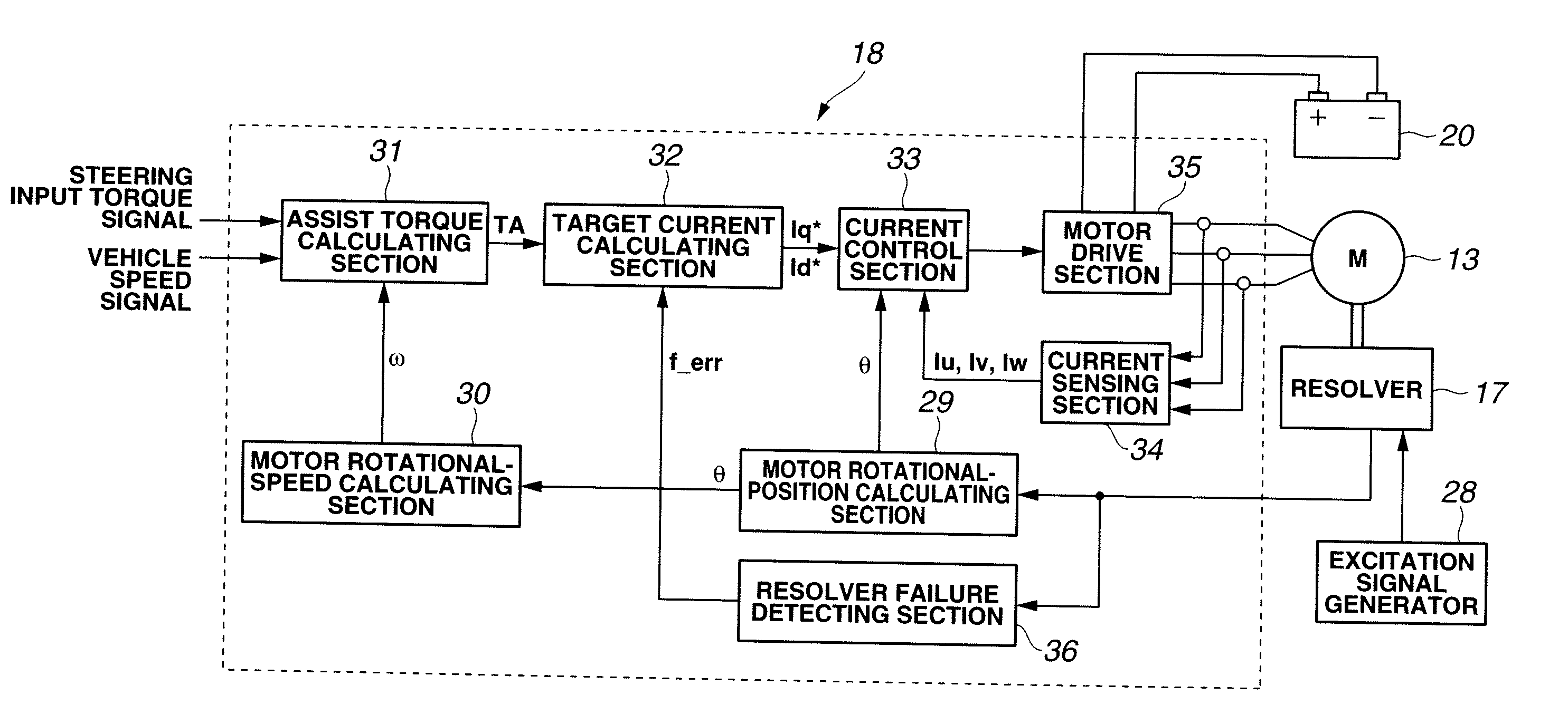
[0069]In the first embodiment, the failure detection apparatus includes the inspection value calculating section 37 configured to calculate the inspection value based on at least one of the sine signal and the cosine signal; the failure detecting section 38 configured to judges whether or not the resolver is in the failure state on the basis of the inspection value; the counting section 39 configured to gradually increase the count value with a lapse of time when the failure detecting section 38 is determining that the resolver is in the failure state, and configured to gradually decrease the count value with a lapse of time when the failure detecting section 38 is determining that the resolver is not in the failure state; and the failure deciding section 40 configured to finally decide that the resolver has caused the failure (improper state) on the basis of the count value.

[0070]Therefore, according to the first embodiment, the count value is gradually increased when the failure d...

second embodiment

[0091]FIG. 10 and FIGS. 11A to 11C are views showing a second embodiment according to the present invention. FIG. 10 is a block diagram showing a resolver failure detecting section (or means) 43. FIGS. 11A to 11C are timing charts showing one example of operations of the resolver failure detecting section 43 when the resolver 17 causes a failure. FIG. 11A is a timing chart showing one example of variations of the sum value of squares, variations of an after-mentioned upper-side inspection value, and variations of an after-mentioned lower-side inspection value. FIG. 11B is a timing chart showing a variation of the count value in the case that the sum value of squares varies as shown in FIG. 11A. FIG. 11C is a timing chart showing a variation of the resolver failure flag f_err in the case that the count value varies as shown in FIG. 11B.

[0092]In this second embodiment, the resolver failure detecting section 43 includes a square-sum calculating section 44 functioning as first inspectio...

third embodiment

[0113]FIG. 14 and FIGS. 15A to 15C are views showing a third embodiment according to the present invention. FIG. 14 is a flowchart showing processing contents of the resolver failure detecting section (or means) 43. FIGS. 15A to 15C are timing charts showing one example of operations of the resolver failure detecting section 43 in the case that the resolver 17 causes a failure. FIG. 15A is a timing chart showing one example of variations of the sum value of squares, variations of the upper-side inspection value, and variations of the lower-side inspection value. FIG. 15B is a timing chart showing a variation of the count value in the case that the sum value of squares varies as shown in FIG. 15A. FIG. 15C is a timing chart showing a variation of the resolver failure flag f_err in the case that the count value varies as shown in FIG. 15B.

[0114]The third embodiment shown in FIG. 14 and FIGS. 15A to 15C is based on the above-explained second embodiment. Additionally in this third embod...


PUM


Abstract

A failure detection apparatus for a resolver outputting a sine signal indicative of sin θ and a cosine signal indicative of cos θ according to a rotational angle θ of a rotator, includes an inspection value calculating section configured to calculate an inspection value based on at least one of the sine signal and the cosine signal; a failure detecting section configured to judge whether the resolver is in a failure state or not on the basis of the inspection value; a counting section configured to gradually increase a count value with a lapse of time when the failure detecting section is determining that the resolver is in the failure state, and configured to gradually decrease the count value with a lapse of time when the failure detecting section is determining that the resolver is not in the failure state; and a failure deciding section configured to finally decide that the resolver has caused the failure on the basis of the count value.

Description

BACKGROUND OF THE INVENTION[0001]The present invention relates to a failure (improper-state) detection apparatus for a resolver configured to output a sine signal indicative of sin θ and a cosine signal indicative of cos θ according to rotational angle θ of a rotator.[0002]Japanese Patent Application Publication No. H09 (1997)-72758 discloses a previously-proposed failure detection apparatus for a resolver. In this technique, a value of sin2 θ+cos2 θ is calculated based on the sine and cosine signals, and it is decided that the resolver has caused a failure when the value of sin2 θ+cos2 θ deviates from a predetermined normal range.SUMMARY OF THE INVENTION[0003]However, when the resolver actually causes a failure, there is a case that the value of sin2 θ+cos2 θ varies outwardly from the normal range and soon inwardly into the normal range and soon outwardly . . . according to the rotational angle θ of the rotator (i.e., repeats inward and outward variations across a boundary of the n...

Claims


Application Information

Patent Timeline
Patent Type & Authority Applications(United States)
IPC IPC(8): G01B7/30H02K29/08
CPCG01D3/08G01B7/30
Inventor YAMAURA, TAMOTSUHAMADA, KENICHIMAKINO, YUTAKA
Owner HITACHI ASTEMO LTD
Why Eureka
Try Eureka