Ultrasonic in-building positioning system based on phase difference array with ranging

a phase difference array and positioning system technology, applied in wave based measurement systems, measurement devices, instruments, etc., can solve the problems of inability to obtain any position measurement at all inside enclosed spaces such as within buildings, inability to obtain reliable positions within heavily built-up urban centers, and increased complexity of digital systems

Active Publication Date: 2009-08-20
INTELLIGENT SCI
View PDF8 Cites 65 Cited by
  • Summary
  • Abstract
  • Description
  • Claims
  • Application Information

AI Technical Summary

Problems solved by technology

Digital systems will have additional complexity based on the digitization, transmission, processing, storage and value-added delivery of digital data and services.
The inherent limitations of GPS technology are that one is unable to obtain reliable positions within heavily built-up urban centers and the inability of obtaining any position measurement at all inside enclosed spaces such as within buildings.
The foregoing accuracy has limited utility for emergency response, particularly in the urban environment.
Such a device enables improved location determination only in those areas where GPS is functional, GPS being limited once again in urban centers and inside buildings.
Although high accuracy in position is possible with longer baselines, this feature is undesirable for in-building, in-air devices.
Again, this approach cannot provide an absolute measure of position and is not the objective of their approach.
The advances to the known art of VSBI described in the Watson et al. patent are not applicable or of value to use in IPS devices.
A limitation of the device shown in the '293 patent is that the background receivers must be scattered around the volume of surveillance.
The system disclosed in the '423 patent does not purport to provide position measurements of the chips with high accuracy; it is deemed sufficient for the most part to localize the devices to within a given room in a building.

Method used


Image

  • Ultrasonic in-building positioning system based on phase difference array with ranging
  • Ultrasonic in-building positioning system based on phase difference array with ranging
  • Ultrasonic in-building positioning system based on phase difference array with ranging

Examples


Embodiment Construction

[0044]1. System Overview

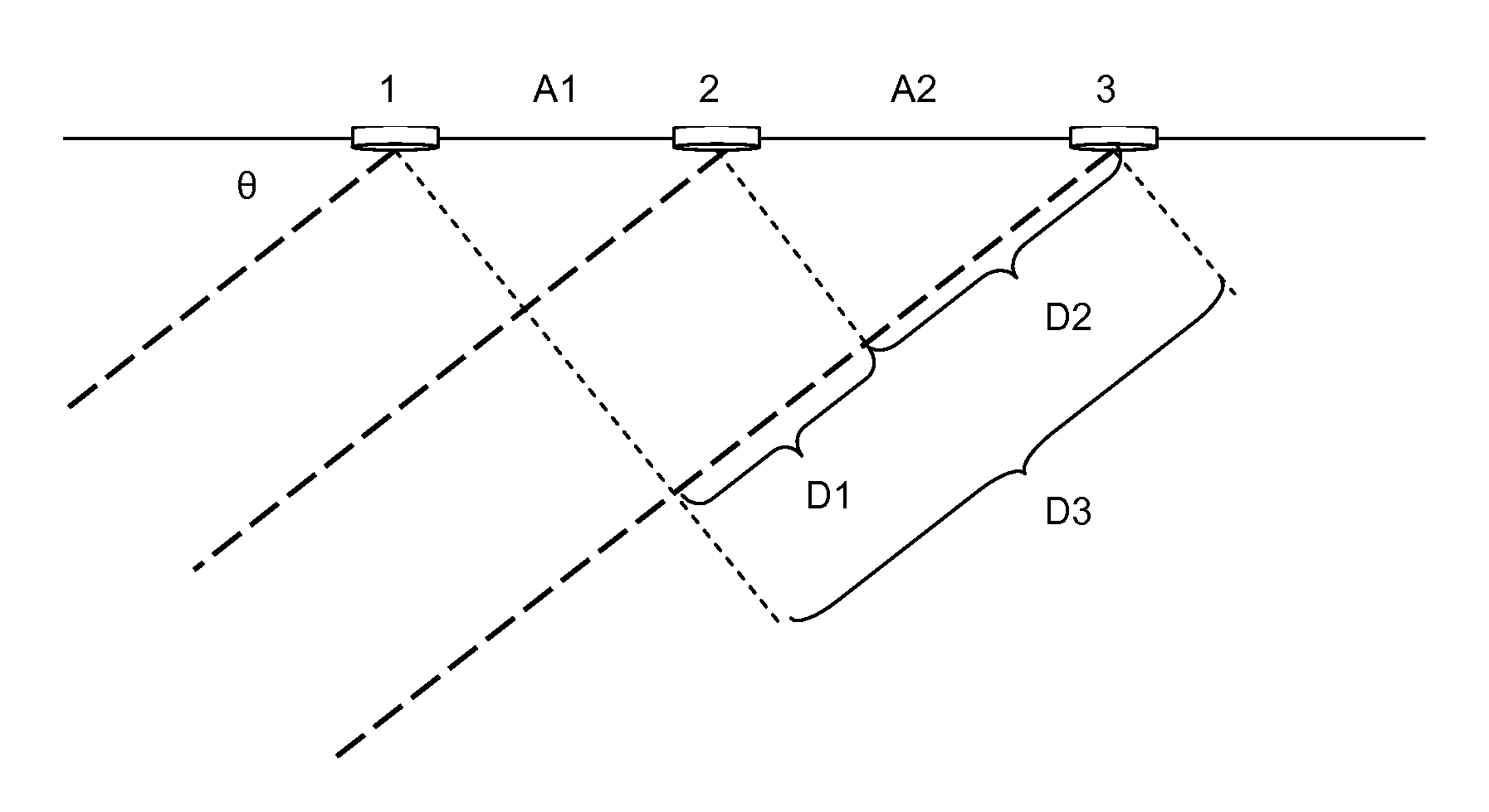
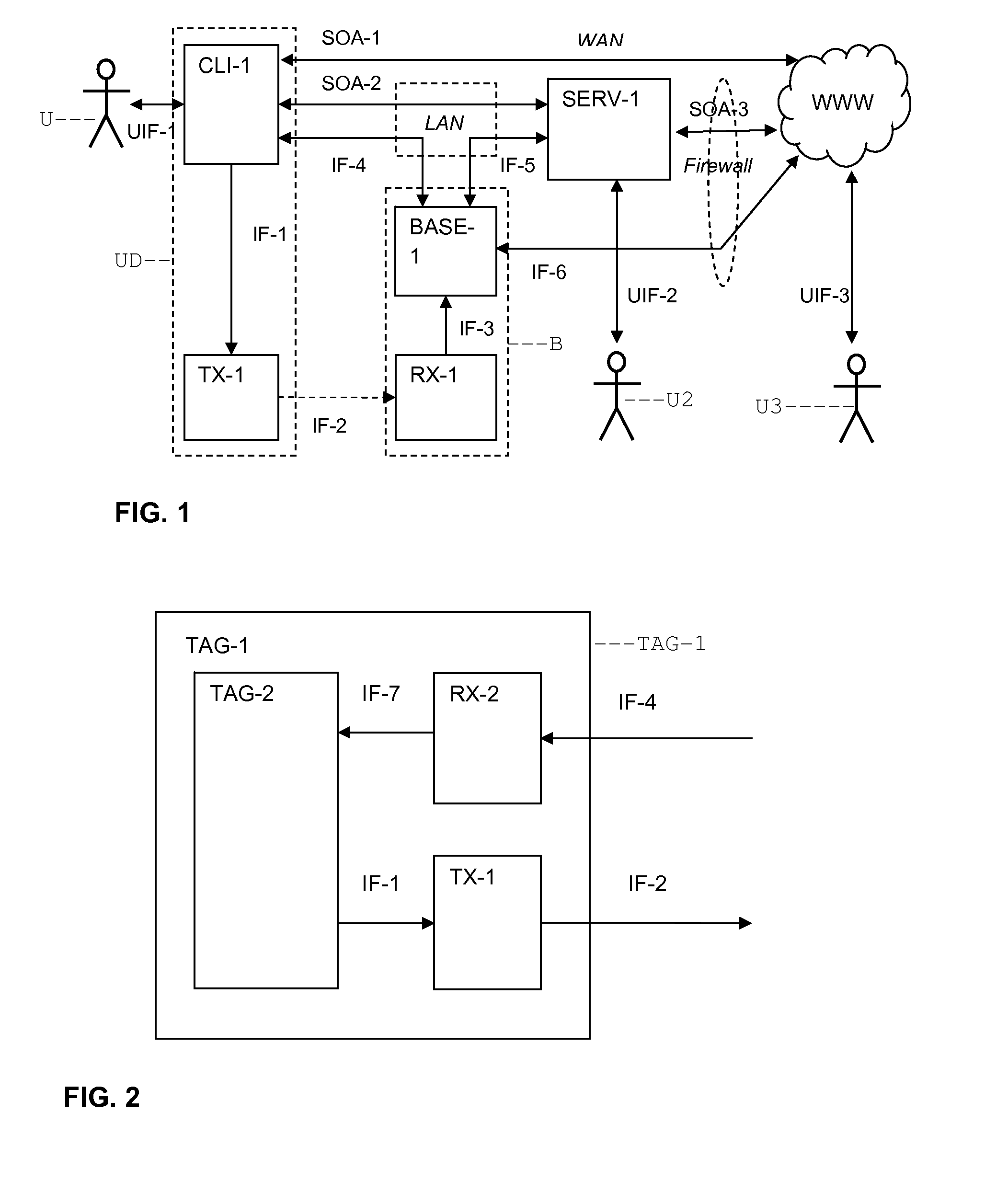
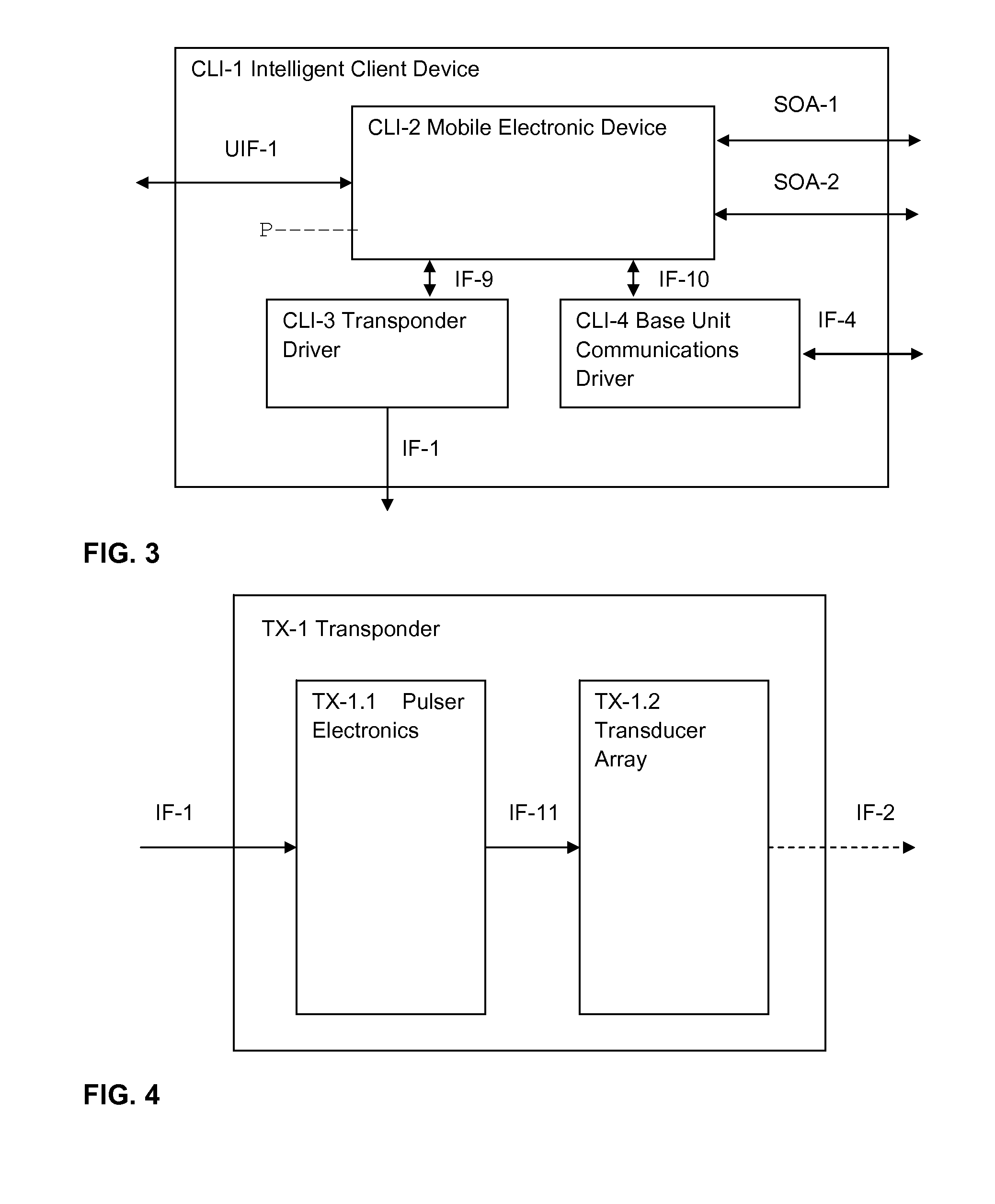
[0045]An ultrasonic based system is described herein for locating a transponder inside an enclosed space such as a building. The positioning accuracy in three dimensions is expected to be on the order of a few centimeters. A “base station” ceiling-located device (e.g., in a building) used in the present system has the ability to both transmit and receive ultrasonic signals. The transmitted signal is received by a transponder in a mobile electronic device. The mobile device is programmed to cause the transponder to transmit a signal in response to the signal received from the base station. The transponder's subsequently emitted signal is received by the base station. From the foregoing event sequence the base station measures the round trip time of the transmitted and detected signals, and also the arrival direction. The transit time and arrival direction information enables the position of the transponder relative to the base station to be located in three di...


PUM


Abstract

A method for determining position of a mobile electronic device includes emitting an acoustic pulse from the position of the mobile electronic device. The acoustic pulse is detected at a known position at three spaced apart locations along each of at least two lines extending in different directions. The range and phase difference of the acoustic pulse between each of the detecting locations is determined. A relative position of the device with respect to the known position is obtained from the range and phase differences.

Description

CROSS-REFERENCE TO RELATED APPLICATIONS[0001]Priority is claimed from U.S. Provisional Application No. 61 / 066,611 filed on Feb. 20, 2008.STATEMENT REGARDING FEDERALLY SPONSORED RESEARCH OR DEVELOPMENT[0002]Not applicable.BACKGROUND OF THE INVENTION[0003]1. Field of the Invention[0004]The invention relates generally to the field of geodetic location of electronic devices within an enclosed space. More particularly, the invention relates to ultrasonic techniques for precise location of mobile electronic devices within the confines of a building.[0005]2. Background Art[0006]Determining the position (e.g., in Cartesian coordinates x, y, z) of mobile electronic devices is important in a number of technical fields, or example, global positioning systems (GPS), indoor positioning (and / or tracking) systems (IPS), context-aware (or location-aware) computing systems, augmented reality systems, ubiquitous (or pervasive) computing systems, range-finding systems, navigation systems, autonomous r...

Claims


Application Information

Patent Timeline
Patent Type & Authority Applications(United States)
IPC IPC(8): G01S3/808
CPCG01S5/22
Inventor GUIGNE, JACQUES Y.STACEY, JAMES A.PACE, NICHOLAS G.
Owner INTELLIGENT SCI
Why Eureka
Try Eureka