Image processing apparatus

a technology of image processing and apparatus, applied in the field of image processing apparatus, can solve the problems of severe color collapse, loss of color balance, and difference between color gradation levels, and achieve the effect of preventing color collapse and distorting color balan

Inactive Publication Date: 2009-08-20
MITSUBISHI ELECTRIC CORP
View PDF4 Cites 23 Cited by
  • Summary
  • Abstract
  • Description
  • Claims
  • Application Information

AI Technical Summary

Benefits of technology

[0008]An object of the present invention is to improve contrast without distorting color balance and without causing severe color collapse.
[0015]Distortion of color balance is prevented by using the same correction parameter for all component values of each pixel.
[0016]Color collapse is prevented by deriving the correction parameter of a pixel from the maximum component value of the pixel, so that the correction parameter does not cause any component value of the pixel to overshoot the maximum value on the gradation correction parameter decision curve.

Problems solved by technology

To prevent this occurrence, a gradation correction is sometimes also performed on the color signal (color difference signals), but this may cause the problem of color collapse, in which differences between color gradation levels are lost.
A problem with this method is that it distorts color balance, because the different primary color components of each pixel tend to be corrected by different amounts.
By multiplying each of the primary color values of a picture element (pixel) by the same ratio (correction parameter) it avoids distortion of color balance, but since the correction parameter is derived from luminance information, the corrected value of a color component may greatly overshoot the maximum gradation limit, causing severe color collapse.

Method used


Image

  • Image processing apparatus
  • Image processing apparatus
  • Image processing apparatus

Examples


embodiment 1

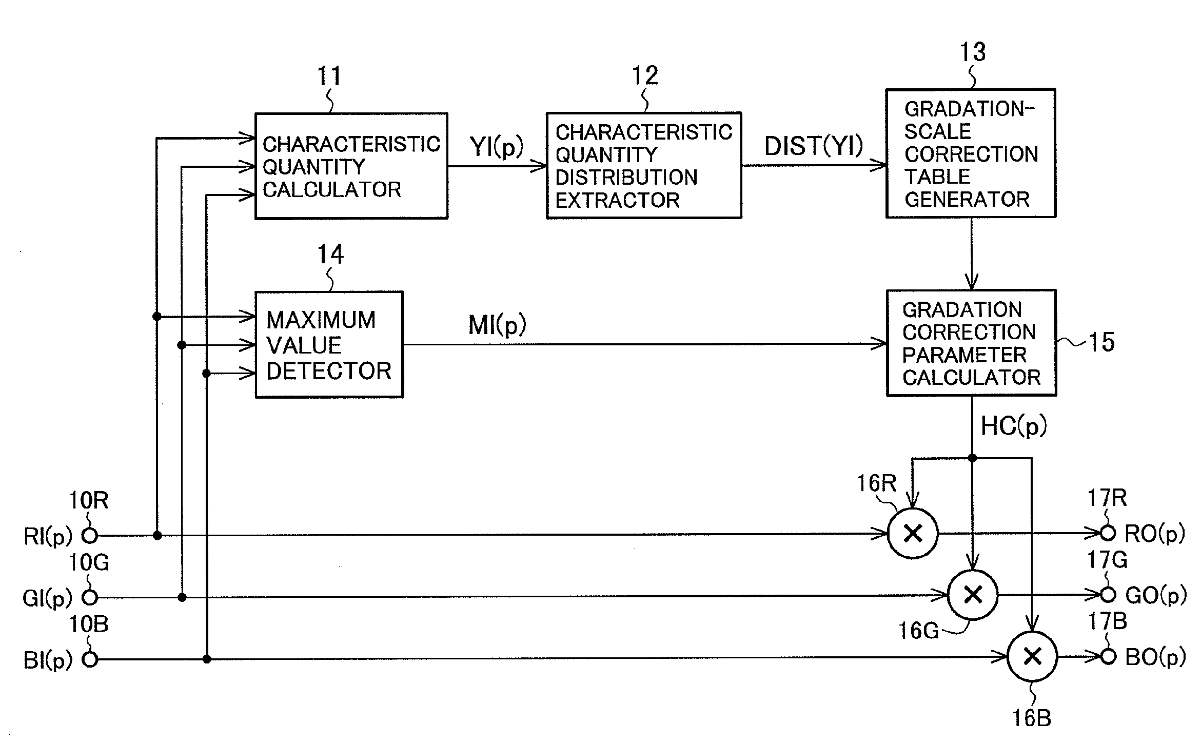
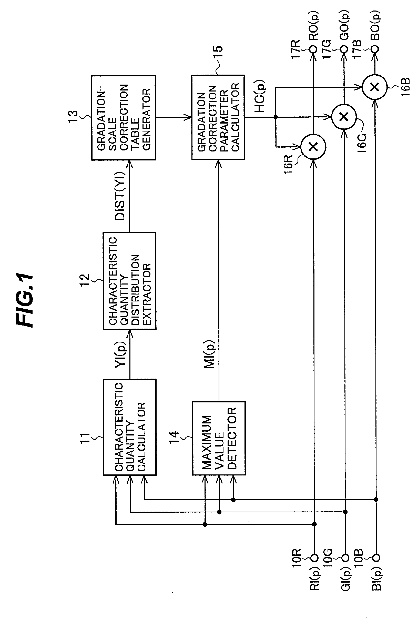
[0028]Referring to FIG. 1, the image processing apparatus includes input terminals 10R, 10G, 10B, a characteristic quantity calculator 11, a characteristic quantity distribution extractor 12, a gradation-scale correction table generator 13, a maximum value detector 14, a gradation correction parameter calculator 15, multipliers 16R, 16G, 16B, and output terminals 17R, 17G, 17B.

[0029]The input terminals 10R, 10G, 10B receive an image signal in a prescribed format used in television and computers. The image signal is divided into frames, each representing one image or screen of, for example, a moving picture. The image signal has a plurality of components. In the present example, these components are red, green, and blue primary color components.

[0030]For each pixel represented by the image signal, the characteristic quantity calculator 11 calculates a characteristic quantity from the primary color components RI, GI, BI of the pixel as received at the input terminals 10R, 10G, 10B and...

embodiment 2

[0079]The image processing apparatus according to Embodiment 2 will now be described with reference to FIG. 9. The structure of the image processing apparatus differs from the image processing apparatus in FIG. 1 only in that the characteristic quantity calculator 11 and characteristic quantity distribution extractor 12 are replaced with a maximum value distribution extractor 18.

[0080]In the image processing apparatus in FIG. 9, the maximum value detector 14 can be regarded as performing the functions of the characteristic quantity calculator 11 in FIG. 1, and the maximum value distribution extractor 18 can be regarded as an instance of the characteristic quantity distribution extractor 12 in FIG. 1. The characteristic quantity calculator 11 in Embodiment 1 calculates an arbitrary characteristic quantity from the primary color signals for each pixel and the characteristic quantity distribution extractor 12 extracts the distribution of the characteristic quantity. Luminance was used ...


PUM


Abstract

An image processing apparatus enhances contrast without producing color balance distortion or color collapse by generating a gradation-scale correction table from a distribution of a characteristic quantity of an input image signal, using the gradation-scale correction table to derive a gradation correction parameter for each pixel from a maximum component value of the pixel, and multiplying all components of the pixel by the gradation correction parameter.

Description

BACKGROUND OF THE INVENTION[0001]1. Field of the Invention[0002]The present invention relates to an image processing apparatus.[0003]2. Description of the Related Art[0004]A conventional image display apparatus disclosed by Nakahigashi et al. in Japanese Patent Application Laid-open No. 2004-342030 improves the contrast of an input signal with components representing values of the three primary colors red, green, and blue by generating a luminance signal from the input signal, generating a gradation-scale correction table from the luminance signal, and multiplying the red, green, and blue component values by a ratio derived from the gradation-scale correction table.[0005]There are two general methods for improving the contrast of a video signal. One general method is to separate the video signal into a luminance component and a color component (e.g., a luminance signal and a pair of color difference signals) and perform a gradation correction on the luminance component. In this meth...

Claims


Application Information

Patent Timeline
Patent Type & Authority Applications(United States)
IPC IPC(8): G06K9/03
CPCG06T5/009G06T2207/10024G06T5/40
Inventor YOSHII, HIDEKIKAGAWA, SHUICHISOMEYA, JUNSUGIURA, HIROAKI
Owner MITSUBISHI ELECTRIC CORP
Why Eureka
Try Eureka