Transmission Clutch Control Apparatus And Method

Active Publication Date: 2009-08-20
GM GLOBAL TECH OPERATIONS LLC
View PDF22 Cites 38 Cited by
  • Summary
  • Abstract
  • Description
  • Claims
  • Application Information

AI Technical Summary

Benefits of technology

[0007]Accordingly, a method is provided for controlling a clutch assembly, including detecting an active fill phase of the clutch assembly, controlling an actual clutch fill pressure for the clutch assembly according to a first set of open-loop control logic when the active fill phase is det

Problems solved by technology

A high torque upshift may require rapid pressurization or fill of the clutch chamber while overcoming compliance to ra

Method used


Image

  • Transmission Clutch Control Apparatus And Method
  • Transmission Clutch Control Apparatus And Method
  • Transmission Clutch Control Apparatus And Method

Examples


Embodiment Construction

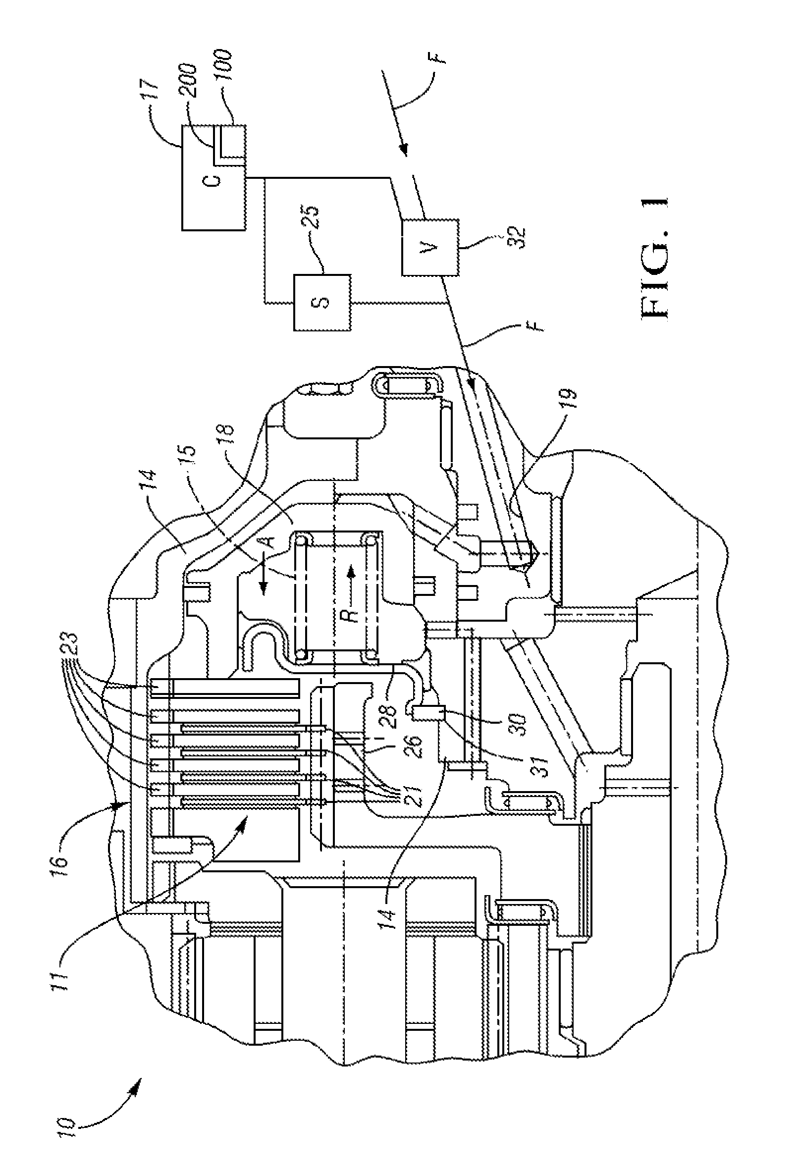
[0021]Referring to the drawings, wherein like reference numbers refer to like components, and beginning with FIG. 1, a clutch assembly 10 operable for transferring torque within a transmission (not shown) includes a clutch pack 11 that is disposed within a clutch housing 14. In the representative clutch assembly 10 of FIG. 1, the clutch housing 14 is splined at 16 to receive the clutch pack 11, although a separate member, such as a clutch drum or another clutch member, may be used in place of the clutch pack 11, as will be understood by those of ordinary skill in the art. The clutch pack 11 has a plurality of clutch plates 23 and a plurality of friction plates 21, and additional clutch assemblies 10 may be used in an automatic transmission, or within a dual-clutch transmission, as needed. Regardless of the number of clutch assemblies 10 used in the clutch assembly 10, the operation of the clutch pack 11 is generally described hereinbelow.

[0022]The clutch plates 23 are interposed bet...


PUM


Abstract

A method for controlling a clutch assembly includes controlling an actual clutch fill pressure using open-loop pressure controls when an active fill phase is detected, and using closed-loop pressure controls when the active fill phase is complete or when an overfill condition is detected. The method supplies the actual clutch pressure according to a second set of open-loop pressure controls when a step in commanded clutch pressure is detected. The method monitors a fill pressure and time during the step, and applies the clutch pressure according to the closed-loop pressure controls when either value equals a corresponding threshold value. A clutch assembly has a piston for compressing clutch disks to initiate a shift event, an algorithm for controlling the shift event, and a sensor for determining an actual clutch pressure during the shift phases. The algorithm switches between closed-loop and open-loop pressure controls in response to different shift phases.

Description

TECHNICAL FIELD[0001]The present invention relates to an apparatus and method for improving the performance of a clutch assembly during an active fill phase and a large commanded clutch pressure step using both open-loop and closed-loop pressure control logic as determined by a detected clutch response and shift phase of the clutch assembly.BACKGROUND OF THE INVENTION[0002]A motor vehicle transmission generally includes a number of gear elements coupling an input shaft and an output shaft, and also includes a number of torque-transmitting devices or clutches that may be selectively engaged to activate certain gear elements and establish a desired speed ratio between the input and output shafts. As used herein, the term “torque-transmitting device” will be used collectively to refer to all clutches, including braking clutches as well as rotating clutches.[0003]Shifting from one speed ratio to another is performed in response to engine throttle level and vehicle speed, and generally i...

Claims


Application Information

Patent Timeline
IPC IPC(8): F16H31/00G06F19/00
CPCF16D48/066F16D2500/3024F16D2500/50684F16D2500/70414Y10T477/70F16D2500/70652Y10T477/753Y10T477/78Y10T477/75F16D2500/7061
Inventor OLSON, BRET M.MOSES, ROBERT L.DLUGOSS, RANDALL B.
Owner GM GLOBAL TECH OPERATIONS LLC
Why Eureka
Try Eureka