Vacuum cleaner and device having ion generator

a vacuum cleaner and generator technology, applied in the field of electric vacuum cleaners, can solve the problems of deterioration of nearby components, especially those formed of resin materials, and achieve the effects of relaxing the feelings of humans, high sterilization effect, and purifying air efficiently and unattended over a wide area

Inactive Publication Date: 2009-08-27
SHARP KK
View PDF12 Cites 7 Cited by
  • Summary
  • Abstract
  • Description
  • Claims
  • Application Information

AI Technical Summary

Benefits of technology

[0009]Incidentally, as the ion generator generates positive and negative ions, it also generates ozone as a byproduct. Accordingly, by treating the part of the suction air passage around the needle-shaped electrode with anti-ozone treatment, it is possible to prevent its deterioration caused by ozone. As is well known, as temperature rises, ozone exerts increasingly high oxidizing power, prompting the deterioration of the components arranged nearby, especially those formed of resin materials. For this reason, to reduce the oxidizing power of the ozone present around the electrode, i.e., the source at which ozone is generated, it is ideal to place the ion generator away from a heat source such as the electric blower.
[0020]Here, only such examples are dealt with in which an electric vacuum cleaner is provided with an ion generator. It is, however, also possible to provide an ion generator for generating ions in any device that is furnished with an air blowing means and a moving means, such as wheels, so that it can be moved around while in use, for example a mobile cleaning robot. This permits the ion generator to be moved around while in operation, and thus makes it possible to purify air efficiently and unattendedly over a wide area or behind an obstacle where a stationary ion generator cannot reach. Thus, it is possible to purify air wherever such a device can be brought into without performing cleaning by suction.

Problems solved by technology

As is well known, as temperature rises, ozone exerts increasingly high oxidizing power, prompting the deterioration of the components arranged nearby, especially those formed of resin materials.

Method used


Image

  • Vacuum cleaner and device having ion generator
  • Vacuum cleaner and device having ion generator
  • Vacuum cleaner and device having ion generator

Examples


fourth embodiment

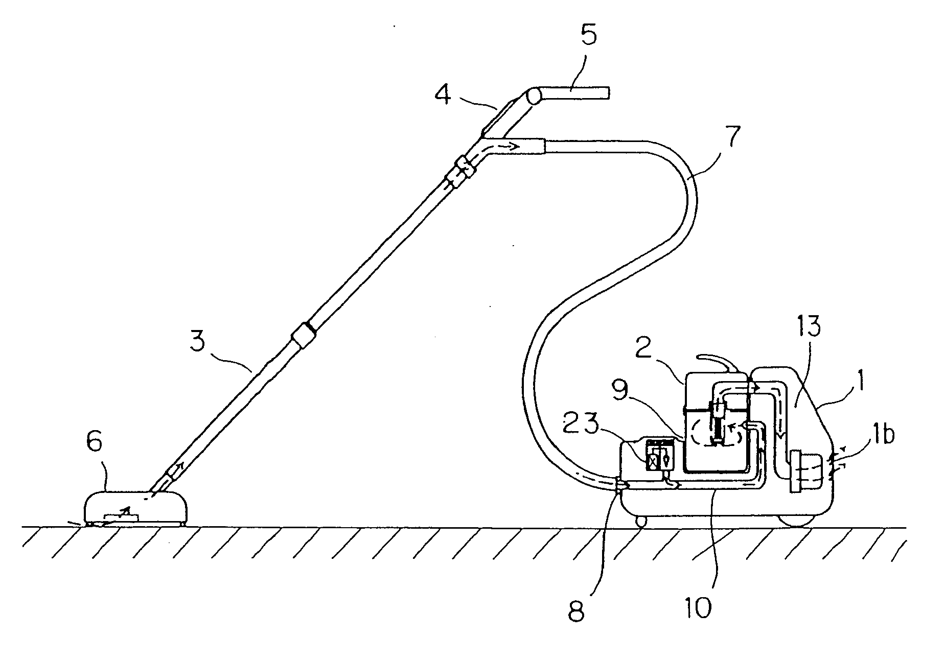
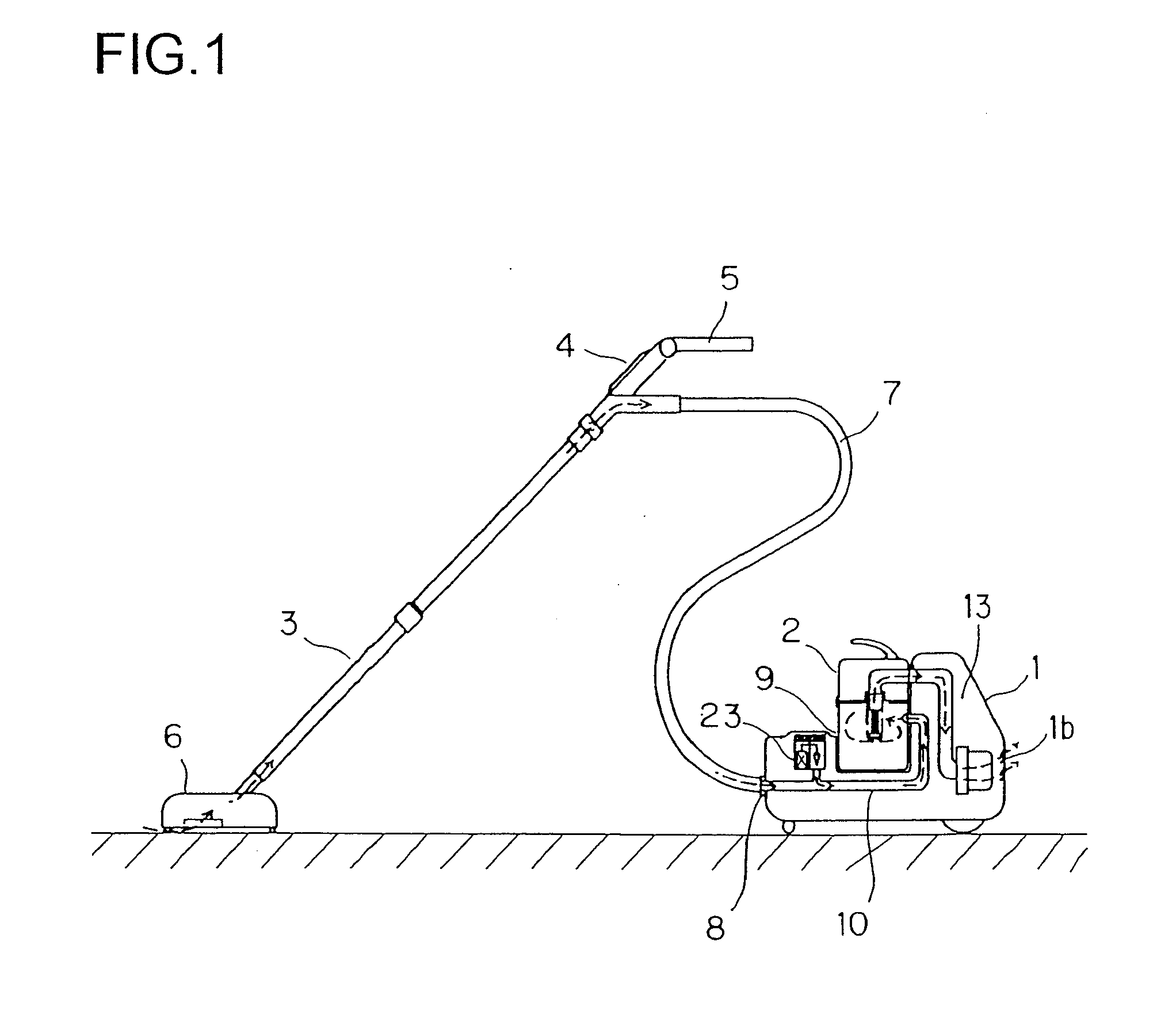
[0138]FIG. 8 is a diagram showing the invention. In this embodiment, the ion generator 231 is disposed on the inside of the rear wall of the body 1 so that ions are discharged into the air that is discharged through the exhaust opening 1b, and are thus discharged into the room by that stream of air. Specifically, near the exhaust opening 1b (for example, closely above the exhaust opening 1b), an ion discharge port 37 is formed to penetrate the rear wall of the body 1, and the ion generator 231 is disposed in close contact with the ion discharge port 37.

[0139]In this construction, when the control panel 4 (see FIG. 1) is so operated as to start operation, the electric blower 14 and the ion generating circuit (not illustrated) are energized, so that the electric blower 14 starts to be driven to suck air in through the nozzle unit 6 (see FIG. 1) and the ion generating circuit (not illustrated) starts to operate to apply a high voltage to the electrode of the ion generator.

[0140]First, ...

seventh embodiment

[0154]FIG. 18 is an external view of the electric vacuum cleaner of the invention, showing its state during storage. FIG. 19 is a sectional view of the body shown in FIG. 18, taken along line A-A. The body 1A of the electric vacuum cleaner of this embodiment incorporates an electric blower 14, is provided with casters 46 on both sides, has a mixing chamber 44 formed by the casters 46, and incorporates an ion generator 231. The body 1A is freely movable in all directions. Moreover, a dust collector 2A is disposed between the body 1A and a nozzle unit 6. To the nozzle unit 6 is connected a suction pipe 301, which is sealed with seals 311a and 311b and is slidably provided relative to the dust collector 2A.

[0155]Alternatively, as shown in FIG. 21, the casters 46 may be provided only around the periphery, with caster covers 601 provided inside them so as to form an ion mixing chamber 44. This permits the ion generator 231 to be maintained easily with only the covers 601 removed.

[0156]Th...

ninth embodiment

[0190]FIG. 25 is a sectional view of the body of the electric vacuum cleaner of the invention. The body shown in FIG. 25 incorporates a first suction passage 10A, an electric blower 14 that drives a motor 54 to rotate a fan 55 and thereby produces a suction stream of air, and a dust collection bag 2A that collects dust that has been sucked in. Moreover, an ion generator 23 is disposed between the dust collection bag 2A and an exhaust opening 1b.

[0191]When a carpet or the like is cleaned with the electric vacuum cleaner having its body 1 constructed as described above, dust, such as animal hair, house mites, mold, and pollen, is sucked in and collected in the dust collection bag 2A, and the chemical substances such as odor-producing substances contained in the air having dust removed therefrom are decomposed by the action of the positive and negative ions discharged from the ion generator 23. Furthermore, ions are discharged into the room by the stream of exhausted air so as to elim...


PUM

PropertyMeasurementUnit
lengthaaaaaaaaaa
lengthaaaaaaaaaa
lengthaaaaaaaaaa

Abstract

When the electrically driven fan (14) of a vacuum cleaner is driven, air containing dust is drawn into the cleaner main body (1) through a hose (7) connected to a hose socket (8) and is exhausted into the outside of the cleaner main body (1) through an exhaust port (1b) via first and second suction passageways (10, 13). Disposed outside the first suction passageway (10) is an ion generator (23), it being arranged that plus and minus ions generated in the ion generator (23) are fed to the air stream flowing in the first suction passageway (10). Since the plus and minus ions kill floating germs in the air stream, the exhaust can be purified.

Description

CROSS REFERENCE TO RELATED APPLICATION[0001]This application is a continuation of U.S. patent application Ser. No. 10 / 487,603 filed Feb. 23, 2004, which is a 371 of PCT / JP02 / 08900, filed on Sep. 2, 2002, which is hereby incorporated herein by reference in its entirety.TECHNICAL FIELD[0002]The present invention relates to an electric vacuum cleaner, and more particularly to an electric vacuum cleaner provided with a sterilizing function.BACKGROUND ART[0003]As a conventional electric vacuum cleaner provided with an ozone generating function, the one disclosed in Japanese Patent Application Laid-Open No. H1-238815 will be described below with reference to FIG. 30. In this conventional electric vacuum cleaner, inside a body 101 thereof is formed a suction air passage 104 that runs from a hose socket 102 formed in the front wall of the body 101 to an exhaust opening 103 formed in the rear wall of the body 101, and in this suction air passage 104 are arranged a dust collection bag 105, a ...

Claims


Application Information

Patent Timeline
Patent Type & Authority Applications(United States)
IPC IPC(8): A47L9/00A47L7/04A61L9/16A61L9/22B01D46/50B01D53/00F24F3/16H01T23/00
CPCA47L7/04A47L9/009A61L9/16A61L9/22B01D46/0028B01D46/0038H01T23/00B01D50/002B01D53/007B01D2267/40B01D2279/55F24F2003/1671F24F2003/1682B01D46/50F24F8/26F24F8/30B01D50/20
Inventor NINOMIYA, KOHJIYAGI, MIKIOHATO, SHIGENORIHAYASHI, KAZUMASAYOSHIMURA, HIROSHISHIMIZU, YOSHIHIRONOJIMA, HIDEOYAGI, HISAHARUNISHIKAWA, KAZUOOHTANI, TETSUYUKI
Owner SHARP KK
Why Eureka
Try Eureka