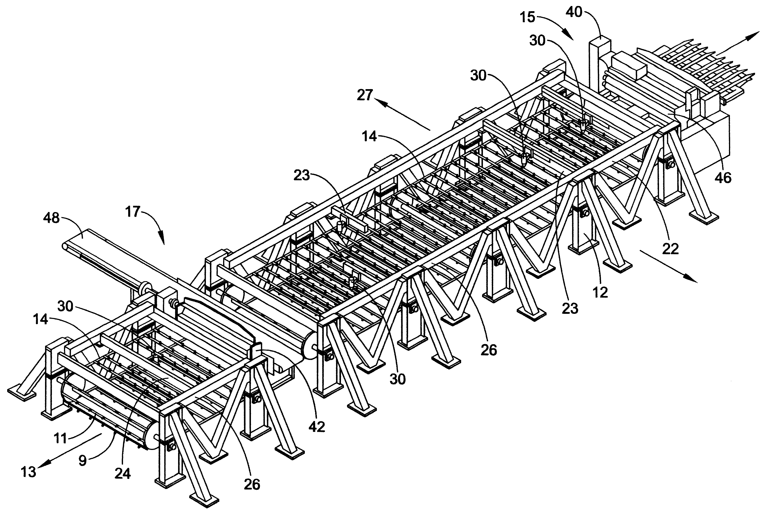
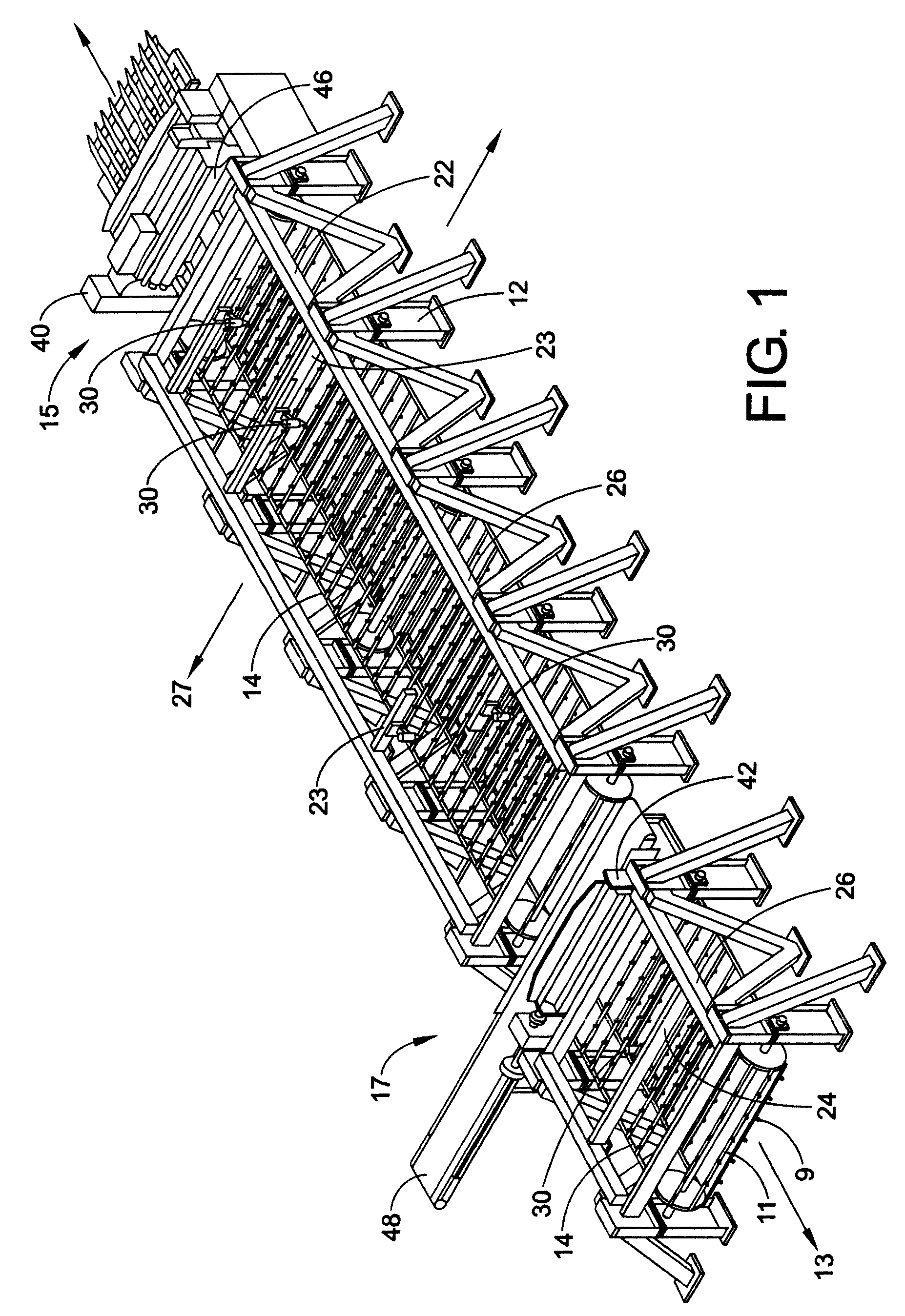
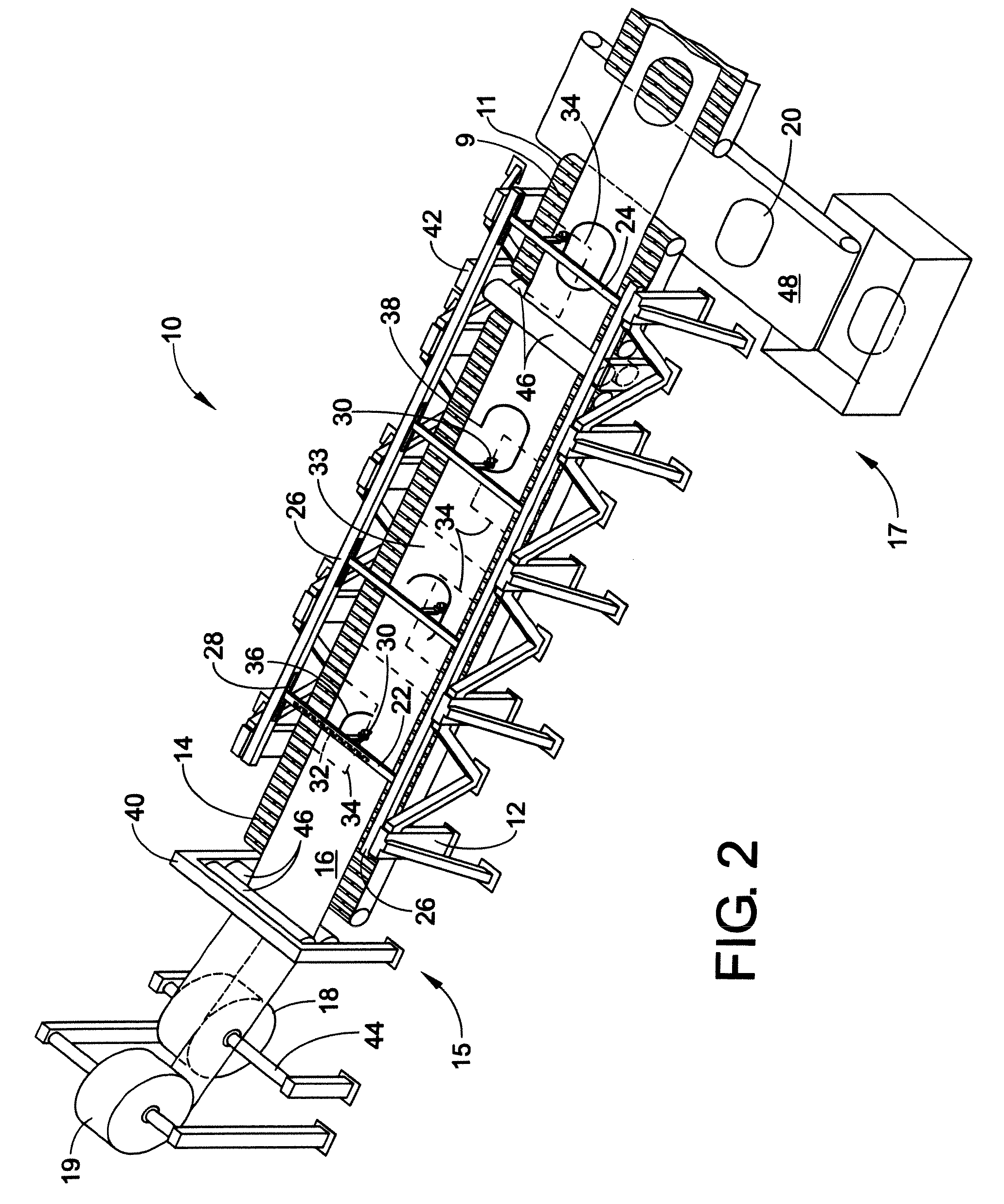
Progressive laser blanking device for high speed cutting

a laser blanking and laser technology, applied in the direction of soldering devices, manufacturing tools, auxillary welding devices, etc., can solve problems such as system inefficiency, and achieve the effect of preventing strip sagging

Active Publication Date: 2009-08-27
LASERCOIL TECH
View PDF17 Cites 49 Cited by
  • Summary
  • Abstract
  • Description
  • Claims
  • Application Information

AI Technical Summary

Benefits of technology

[0009]The laser blanking device further includes at least two sets of pinch rollers. A first pair of opposed pinch rollers is positioned adjacent to the first end of the conveyor support frame between the coil stock and the pin conveyor. A second pair of opposed pinch rollers is positioned adjacent to a second end of the c

Problems solved by technology

This system is inefficient due to the repeated start-and-stop operations of the conveyor; he

Method used


Image

  • Progressive laser blanking device for high speed cutting
  • Progressive laser blanking device for high speed cutting
  • Progressive laser blanking device for high speed cutting

Examples


Embodiment Construction

[0025]For purposes of this disclosure, the terms “blank” and “developed blank” mean a final product or a finished part formed from the strip of coil stock. A developed blank may comprise a simple profile, or it may include complex contours and holes formed there through. To achieve the final shape of the blank, the material removed from any holes is moved away from the strip. This removed material is referred to herein as “cut-out”, “scrap”, or “all-fall”.

[0026]As used herein for purposes of enablement, the term “perimeter” designates the profile shape being cut. For purposes of enablement, a “perimeter portion” is not assigned solely to an entire perimeter of the developed blank or scrap part; rather; the term “perimeter portion” used herein refers to the partial or complete profile aimed to be cut by any one specific laser. This profile can be part of an outer circumference of the (developed or scrap) part, which mainly designates a total outer-shape of the part. The perimeter can...


PUM

PropertyMeasurementUnit
Lengthaaaaaaaaaa
Speedaaaaaaaaaa
Widthaaaaaaaaaa

Abstract

A laser blanking device for high speed cutting of a rapidly fed strip of coil stock includes a pin conveyor traveling a recurring loop along a longitudinal axis. At least two moveable gantries are supported above the pin conveyor. Each gantry is capable of moving at least a limited length along the longitudinal axis. At least one moveable laser head is suspended on each gantry, and the laser heads are capable of moving along the corresponding gantry along multiple axes transverse to or parallel to the longitudinal axis of the device. The device further has an entry pinch roll assembly and a second pinch roll assembly positioned at opposed ends of the conveyor. A pair of pinch rollers cooperates with each pinch roll assembly to apply tension to the strip traveling therebetween. Each pinch roller continually feeds the moving strip along the conveyor while the laser heads situated between the pinch roll assemblies move and progressively cut a perimeter portion of a blank or cut-out from the moving strip.

Description

[0001]The present application claims priority from both Provisional Application No. 61 / 066,369, filed Feb. 20, 2008, and Provisional Application No. 61 / 066,601, filed Feb. 21, 2008, both of which are incorporated by reference herein.BACKGROUND OF THE DISCLOSURE[0002]The present disclosure relates generally to a progressive laser blanking device for high speed cutting of material and, more specifically, to a device that utilizes synchronized laser cutting operations along multiple axes and on a continuously moving strip of material.[0003]Existing press-based mechanical blanking systems perform material cutting operations on flat, stationary sections of strips of material positioned underneath a press. Typically, a strip of material unreels from a coil stock, and the strip is straightened as it is fed into an automatic feeder. The feeder feeds the strip to a belt conveyor, which then moves the strip along the belt until it is situated directly beneath the mechanical press. Movement of...

Claims


Application Information

Patent Timeline
IPC IPC(8): B23K26/10B23K26/38
CPCB23K26/0846B23K26/0869B23K2201/16B23K37/0235B23K37/0408B23K26/38B23K26/032B23K26/0876B23K26/16B23K2101/16
Inventor BECK, KIMMCMURTRIE, KURTMARANDO, RICHARD A.
Owner LASERCOIL TECH
Why Eureka
Try Eureka