Method for forming friction welded compression based tubular structures

Inactive Publication Date: 2009-08-27
ARCONIC INC
View PDF16 Cites 11 Cited by
  • Summary
  • Abstract
  • Description
  • Claims
  • Application Information

AI Technical Summary

Benefits of technology

[0007]In one embodiment, the present invention provides a method for of making a compression based tubular structure using friction welding that improves the durability and structural integrity of tubular structures via increased resistance to tension and fatigue types of loading and in some cases resistance to corrosion. The method comprises machining square a first end and a second end of a first pipe, machining square a first end and a second end of a second pipe, friction welding the second end of the first pipe to the first end of the second pipe to create a joint, machining square the first end of the first pipe and the second end of the second pipe, machining square a flanged-end of a flange, friction welding the flanged-end of the flange to the first end of the first pipe to create a second joint, machining square the second end of the second pipe, machining square a flanged-end of a second flange, friction welding the flanged-end of the second flange to the second end of the second pipe to create a third joint, and connecting a plurality of tension rods between the flange and the opposite second flange where the compression based tubular structure has at least one structural joint using the friction welding process.
[0014]Accordingly, it is one embodiment of the invention to provide a method for making compression based tubular structures using friction welding that create highly reliable and consistent weld quality and great performance with decreased weight load by using thinner pipes.

Problems solved by technology

Thus, the pipes at and near the top of the casing tube are subjected to a very large pulling force.
In many instances, if no corrective measures are taken, this pulling force may be sufficient to stretch the carbon steel pipes near the top of the casing tube beyond their elastic limit and possibly lead to their catastrophic failure (e.g. rapture of seams, and joints such as welds).

Method used


Image

  • Method for forming friction welded compression based tubular structures
  • Method for forming friction welded compression based tubular structures
  • Method for forming friction welded compression based tubular structures

Examples


Embodiment Construction

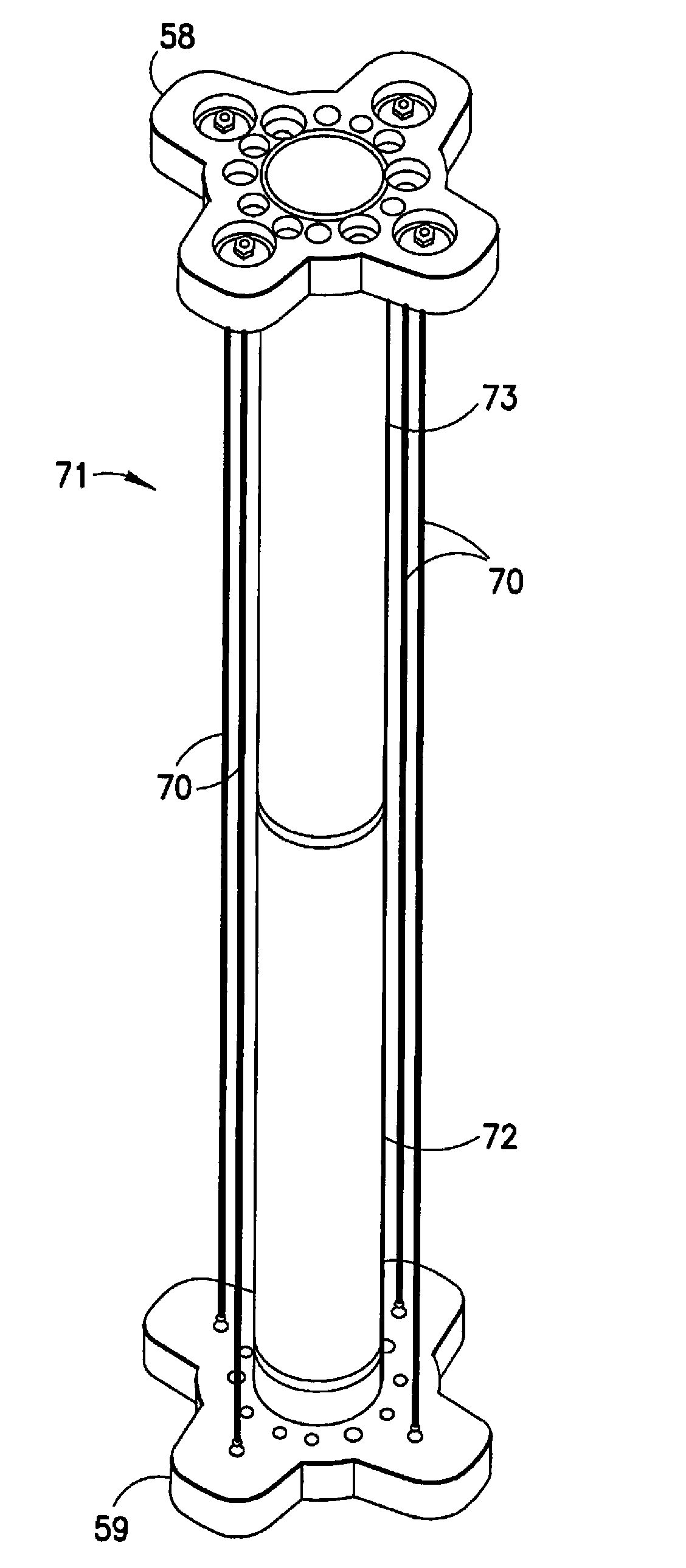
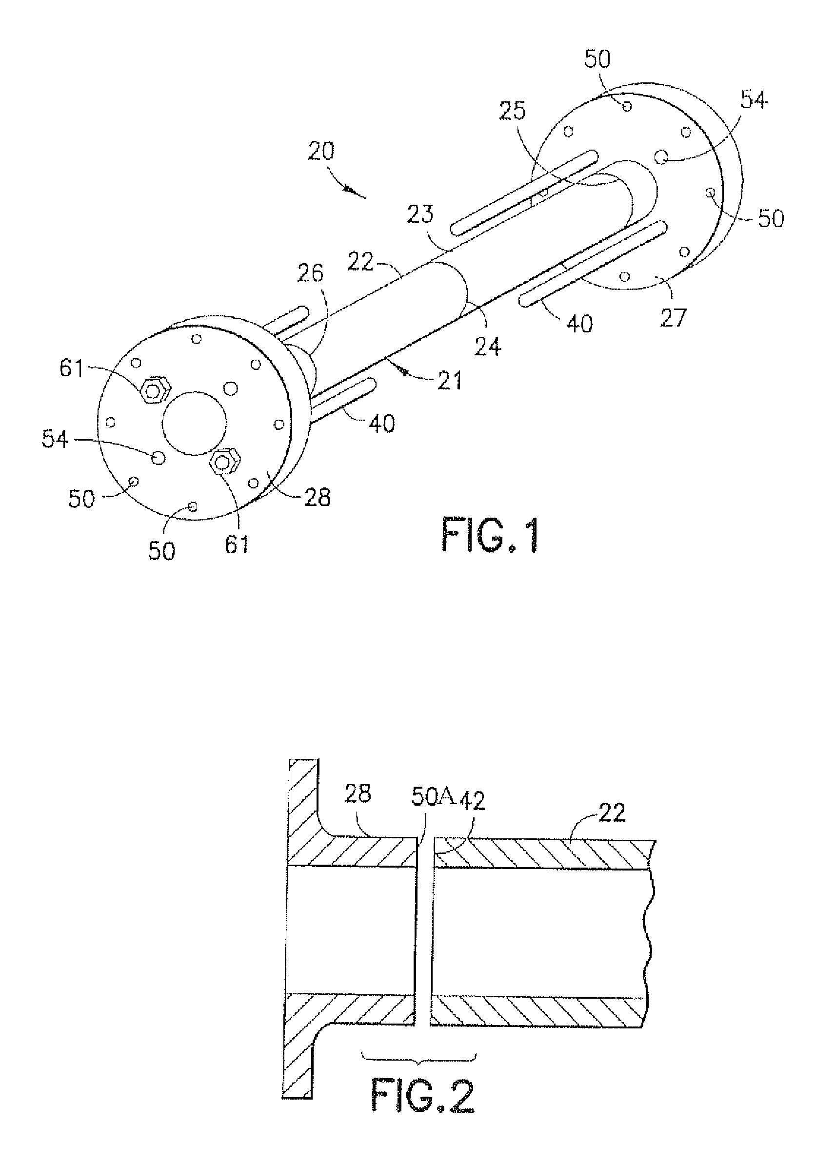
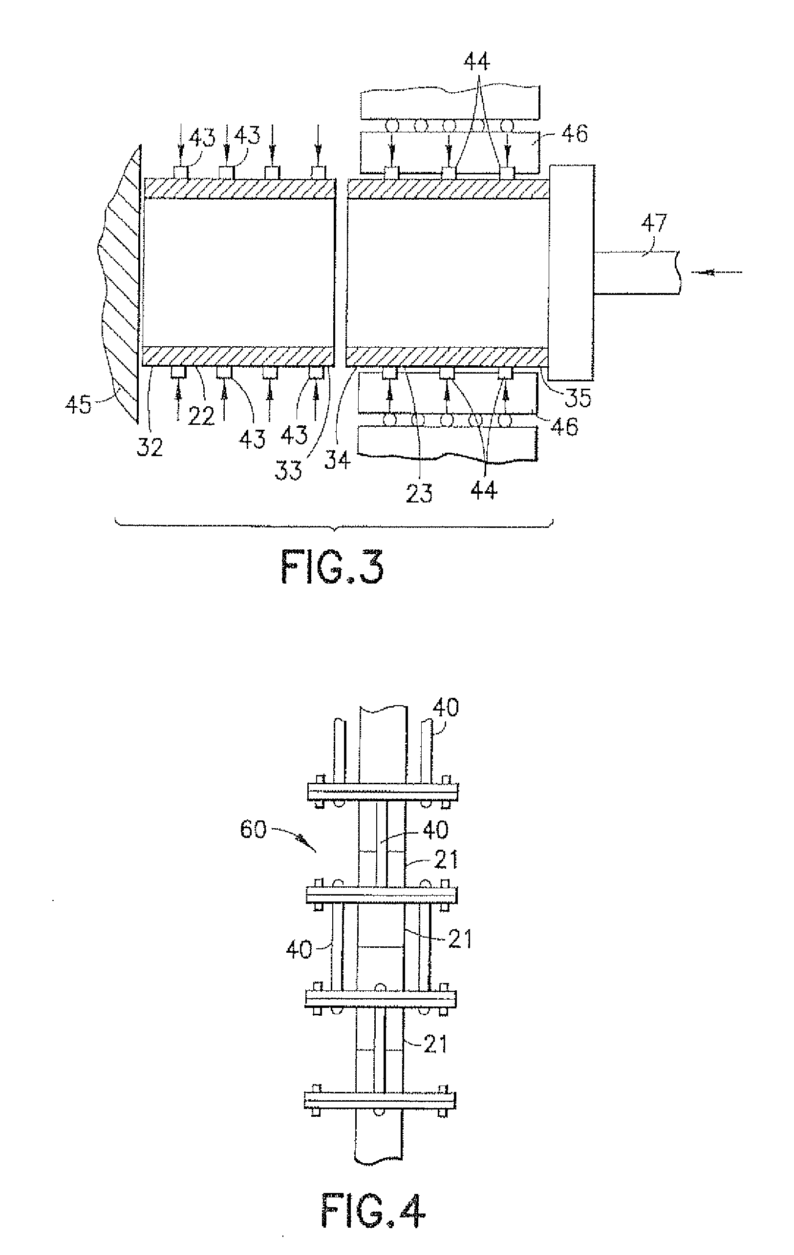
[0030]The present invention discloses a method for making compression based tubular structures using friction welding that results in improving the reliability of welds, corrosion resistance and decreasing the weight load of a tubular structure. The method of making the compression based tubular structure comprises machining square a first end and a second end of a first pipe, machining square a first end and a second end of a second pipe, friction welding the second end of the first pipe to the first end of the second pipe to create a joint, machining square the first end of the first pipe and the second end of the second pipe, machining square a flanged-end of a flange, friction welding the flanged-end of the flange to the first end of the first pipe to create a second joint, machining square the second end of the second pipe, machining square a flanged-end of a second flange, friction welding the flanged-end of the second flange to the second end of the second pipe to create a th...


PUM

PropertyMeasurementUnit
Lengthaaaaaaaaaa
Tensionaaaaaaaaaa
Durabilityaaaaaaaaaa

Abstract

A method of making a compression based tubular structure having at least one structural joint using the friction welding process to improve the durability of tubular structures and structural integrity via increased resistance to tension and fatigue type loading and resistance to corrosion. A method of making a compression based tubular structure having at least one structural joint using the friction welding process is provided. In addition, a compression based tubular structure is provided. The compression based tubular structure comprises at least one tubular structure joint, at least one pair of flanges that surround each tubular joint, and a plurality of tension rods that connect the pair of flanges that surround the tubular structure joint.

Description

BACKGROUND OF THE INVENTION[0001]In one embodiment, the present invention relates to a method for making compression based tubular structures using friction welding. In another embodiment, the invention pertains to a method for making compression based tubular structures, such as risers for the oil-drilling industry, sleeves for cannons and any other compression based tubular structures that are friction welded. In a further embodiment, compression based tubular structures may consist of pipes / tubes that are joined end to end, pipe / tube to flange ends that are joined end to end and / or pipe / tube to hollow-end cap that are joined end to end by friction welding for use between a well platform and an oil well or gas well located on the sea floor.[0002]When an oil well or a gas well located on the sea floor is drilled from a platform, steel pipes of a predetermined length are connected together, end to end to form a casing tube which is lowered from the platform to the sea floor. The cas...

Claims


Application Information

Patent Timeline
IPC IPC(8): B23K20/12F16L9/22
CPCB23K20/12B23K20/129E21B17/017B23K2201/10E21B17/012B23K2201/06B23K2101/06B23K2101/10
Inventor STOL, ISRAEL
Owner ARCONIC INC
Why Eureka
Try Eureka