Radially outward flowing air-blast fuel injector for gas turbine engine

a gas turbine engine and fuel injector technology, which is applied in the direction of machines/engines, combustion types, lighting and heating apparatus, etc., can solve the problem of not retaining any trapped fuel, and achieve the effect of greatly enhancing the degree or rate of fuel/air mixing in the atomizer of the subject invention and reducing the levels of pollutant emissions

Active Publication Date: 2009-08-27
ROLLS ROYCE PLC
View PDF20 Cites 24 Cited by
  • Summary
  • Abstract
  • Description
  • Claims
  • Application Information

AI Technical Summary

Benefits of technology

[0008]The subject invention is directed to a radially outwardly flowing air-blast fuel injector for gas turbine engines. More particularly, the subject invention is directed to an air-blast type fuel atomizer wherein fuel issuing from the fuel swirler does not flow radially inward, as in prior art air-blast type atomizers, but rather the fuel issuing from the fuel swirler flows radially outward and exits the fuel swirler at a diameter that is greater than the diameter of the fuel swirl slots. As a result of this unique configuration, the degree or rate of fuel / air mixing in the atomizer of the subject invention is greatly enhanced, thereby reducing the levels of pollutant emissions (e.g., oxides of nitrogen).

Problems solved by technology

Thus, it will not retain any trapped fuel, which can form carbon (e.g., coking) under the high operating temperatures of the gas turbine.

Method used


Image

  • Radially outward flowing air-blast fuel injector for gas turbine engine
  • Radially outward flowing air-blast fuel injector for gas turbine engine
  • Radially outward flowing air-blast fuel injector for gas turbine engine

Examples


Embodiment Construction

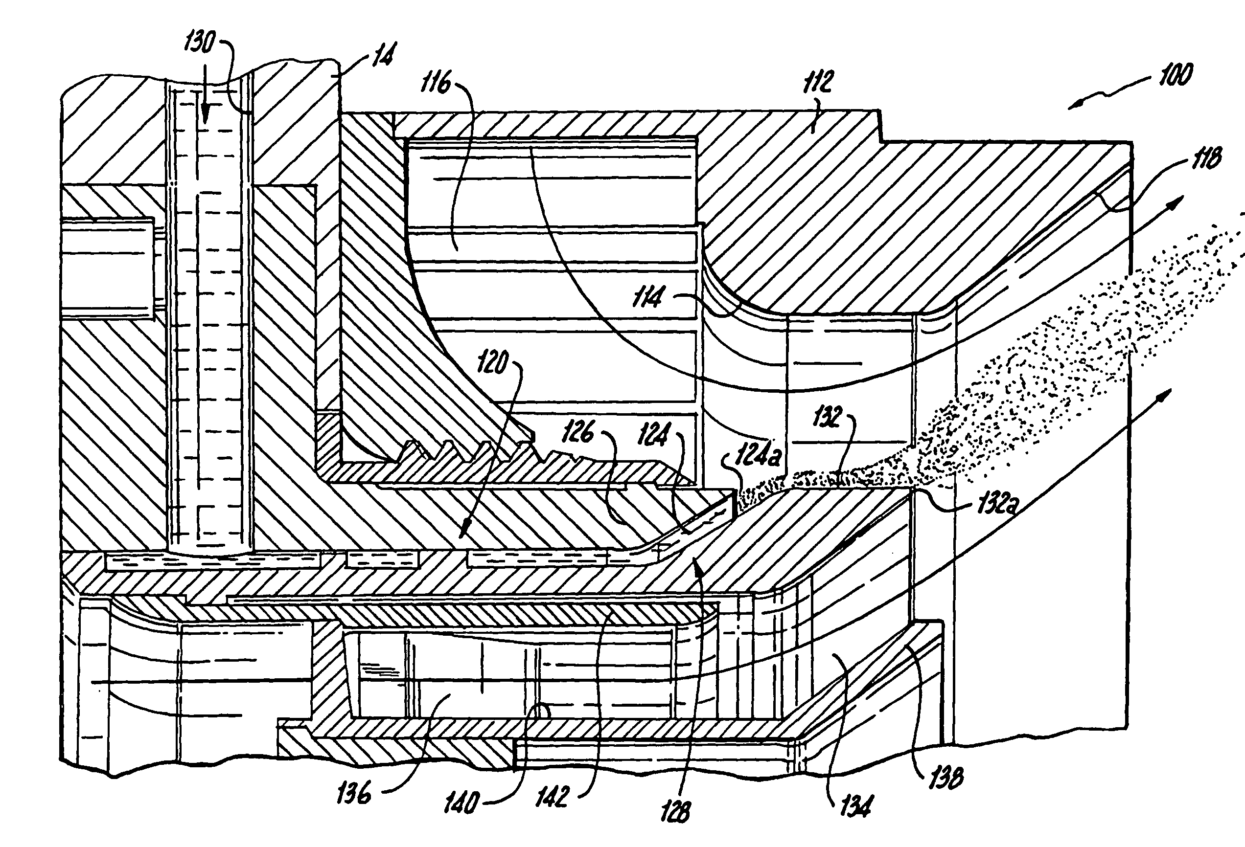
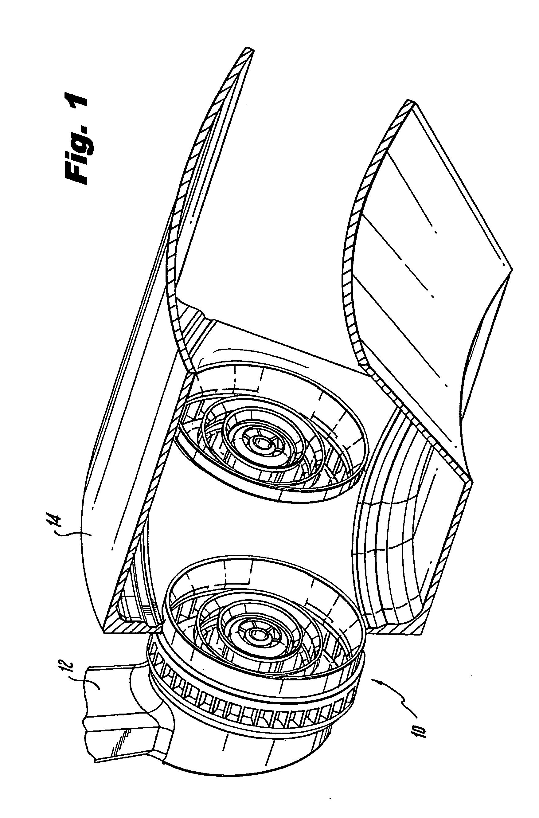
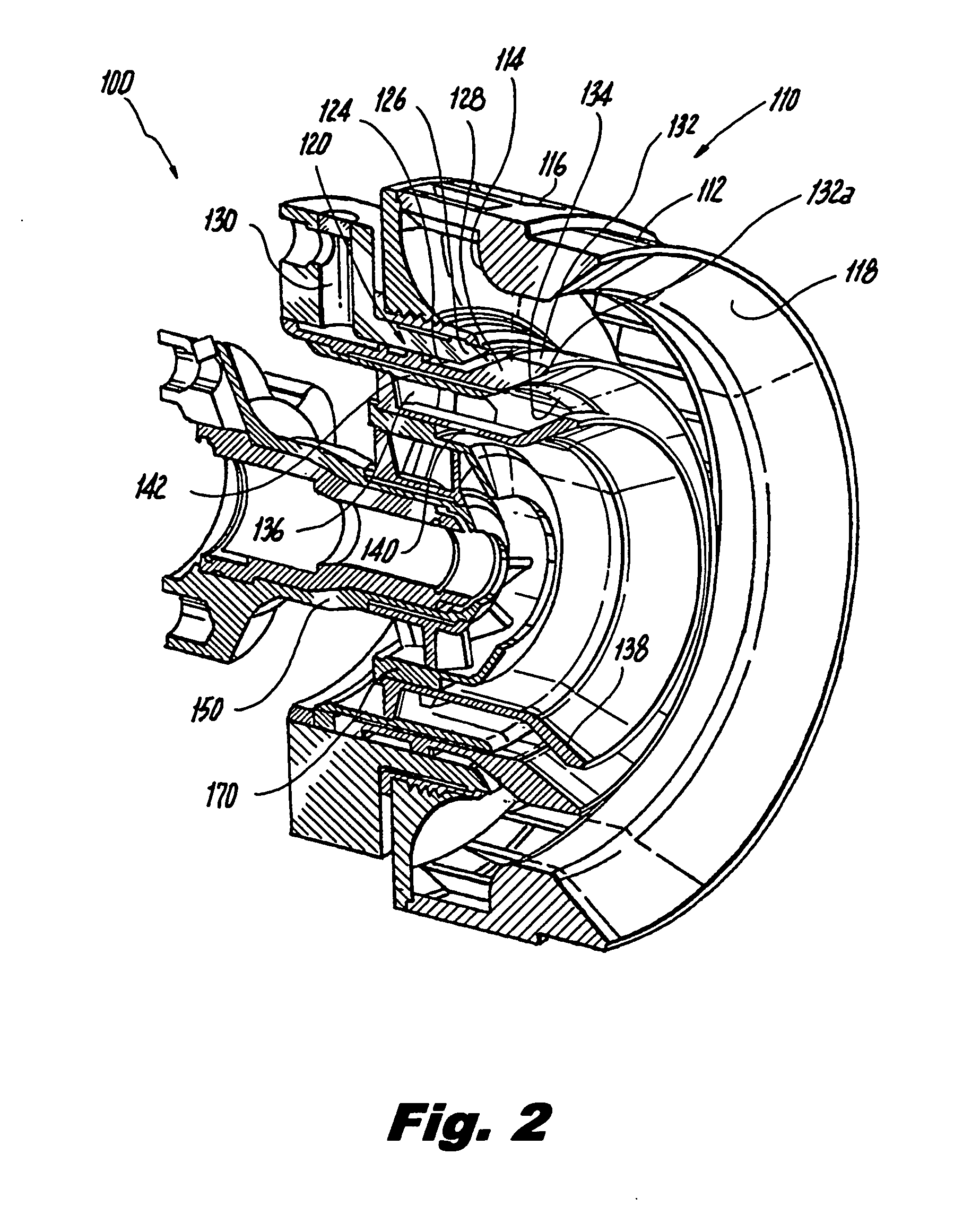
[0029]Referring now to the drawings, wherein like reference numerals identify or otherwise refer to similar structural features or elements of the various embodiments of the subject invention, there is illustrated in FIG. 1 a radially outwardly flowing air-blast fuel nozzle constructed in accordance with the subject invention and designated generally by reference numeral 10. As illustrated, fuel nozzle 10 is a two-stage nozzle provided at the end of a feed arm 12 of a fuel injector, for issuing atomized fuel into the combustion chamber 14 of a gas turbine engine.

[0030]As discussed further below, fuel nozzle 10 is particularly well adapted and configured to effectuate two-stage combustion within a gas turbine engine for enhanced operability and lean combustion for low pollutant emissions. In particular, fuel nozzle 10 is configured as a multi-staged, lean direct injection (LDI) combustion system, through which 60-70% of the combustion air flows through the nozzle with the balance of ...


PUM


Abstract

An air-blast fuel injector is disclosed which includes an outer air circuit having an exit portion, an inner air circuit having an outlet configured to direct air toward the exit portion of the outer air circuit, and a fuel circuit radially outboard of the inner air circuit and having an exit communicating with the outer air circuit upstream from the exit portion of the outer air circuit.

Description

BACKGROUND OF THE INVENTION[0001]1. Field of the Invention[0002]The subject invention is directed to a fuel injector for a gas turbine engine, and more particularly, to a radially outwardly flowing air-blast fuel injector for a gas turbine engine.[0003]2. Description of Related Art[0004]Air-blast fuel injectors for issuing atomized fuel into the combustor of a gas turbine engines are known in the art. Also known in the art are staged fuel injectors designed to improve engine efficiency. Here, the combustion process is divided into two or more stages or zones, which are generally separated from each other, either radially or axially, but still permitted some measure of interaction. For example, the combustion process may be divided into a pilot combustion stage and a main combustion stage. Each stage is designed to provide a certain range of operability, while maintaining control over the levels of pollutant formation. For low power operation, only the pilot stage is active. For high...

Claims


Application Information

Patent Timeline
Patent Type & Authority Applications(United States)
IPC IPC(8): B05B1/02
CPCF23C2201/20F23R3/28F23R3/14F23D2900/11101
Inventor THOMSON, NEAL A.BUELOW, PHILIP E.O.BRETZ, DAVID H.
Owner ROLLS ROYCE PLC
Why Eureka
Try Eureka