Hydraulic Suspension System

a suspension system and hydraulic technology, applied in the direction of shock absorbers, mechanical equipment, transportation and packaging, etc., can solve the problems of deterioration in riding comfort and/or stability during riding, and the corresponding decrease in the force of deadening or damping the vibration of the vehicle body, so as to achieve a soft riding feel

Active Publication Date: 2009-08-27
KUBOTA LTD
View PDF3 Cites 20 Cited by
  • Summary
  • Abstract
  • Description
  • Claims
  • Application Information

AI Technical Summary

Benefits of technology

[0033]For instance, it may be arranged such that the harder the suspension set by the setter, the lower the threshold for the cylinder oil passage pressure. This makes easer the switchover from the orifice of the flow control valve for establishing communication between the hydraulic cylinder and the accumulator from the one having the large flow passage cross section area to the one having the small flow passage cross section area and makes more difficult the switchover from the one having the small flow passage cross section area to the one having the large flow passage cross section area. Conversely, it may be arranged the softer the suspension set by the setter, the higher the threshold for the cylinder oil passage pressure. This makes more difficult the switchover from the orifice of the flow control valve for establishing communication between the hydraulic cylinder and the accumulator from the one having the large flow passage cross section area to the one having the small flow passage cross section area and makes easier the switchover from the one having the small flow passage cross section area to the one having the large flow passage cross section area.
[0034]That is to say, when the setter sets harder setting for the suspension, this makes higher the chance of using the one having the small flow passage cross section area as the orifice of the flow control valve establishing communication between the hydraulic cylinder and the accumulator, so that generally hard riding feel can be provided. Conversely, when the setter sets softer setting for the suspension, this makes higher the chance of using the one having the large flow passage cross section area as the orifice of the flow control valve establishing communication between the hydraulic cylinder and the accumulator, so that generally soft riding feel can be provided.

Problems solved by technology

Therefore, if there occurs increase in the front load of the vehicle body due to e.g. attachment of an implement or increase in the work load and there occurs increase in the spring constant of the suspension in proportion thereto, the damping ratio of the suspension becomes smaller relatively, which leads to corresponding decrease in the force for deadening or damping vehicle body vibration.
As a result, there occurs deterioration in the riding comfort and / or in stability during vehicle run.

Method used


Image

  • Hydraulic Suspension System
  • Hydraulic Suspension System
  • Hydraulic Suspension System

Examples


Embodiment Construction

[0044]Next, preferred embodiments of the present invention will be described with reference to the accompanying drawings. It is understood that any one or more characterizing features of one embodiment can be used in any desired combination with one or more characterizing features of any further embodiment and that such combinations, as long as the combination not resulting in contradictions, are also encompassed within the scope of the present invention.

[0045]In the instant embodiment, a hydraulic suspension system relating to the present invention is applied to a tractor.

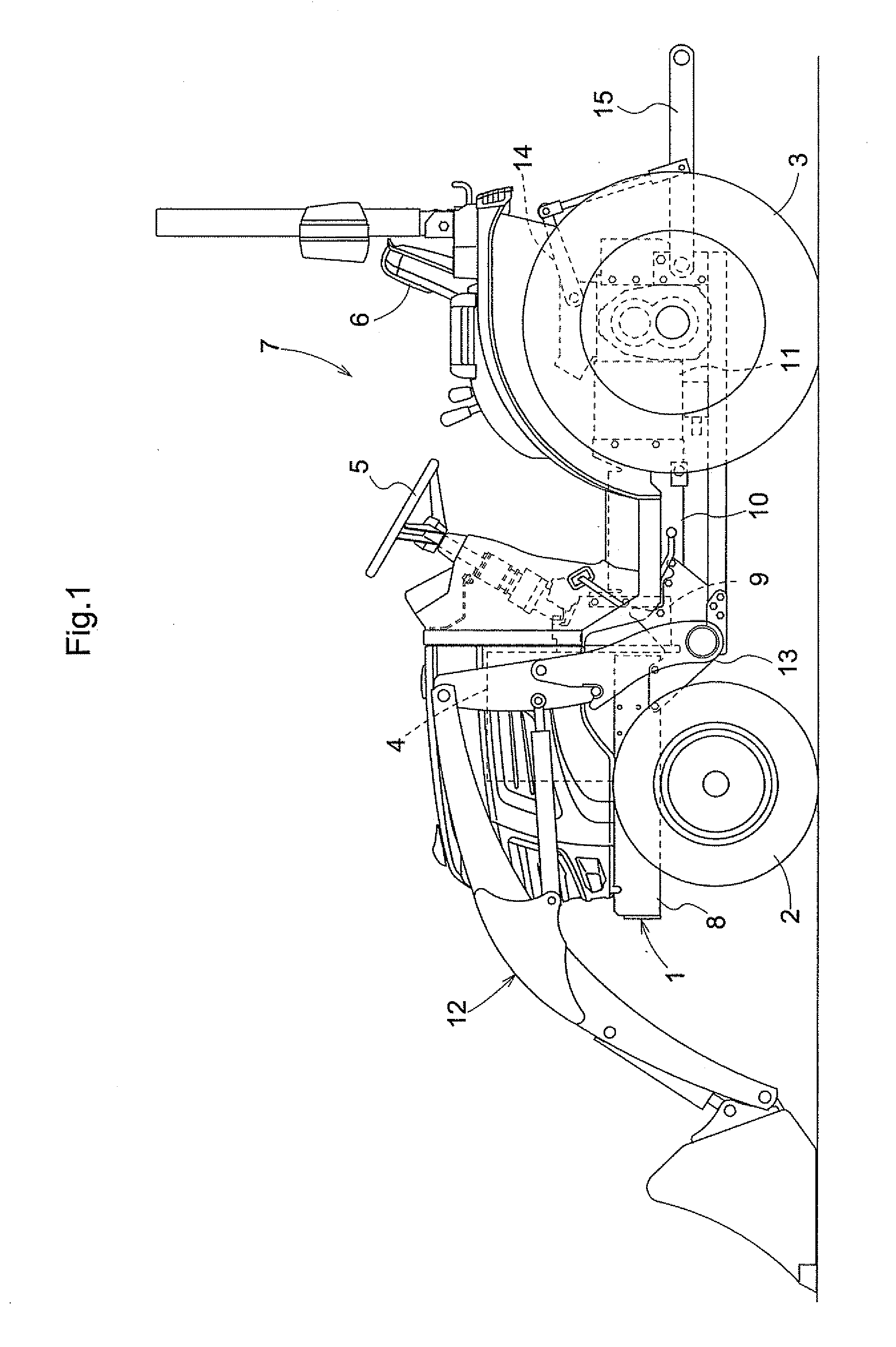
[0046]FIG. 1 is an overall side view of the tractor. As shown, the tractor comprises a four-wheel drive type vehicle including a vehicle body frame 1, an engine 4 mounted on the vehicle body frame 1, and a pair of right and left front wheels 2 and a pair of right and left rear wheels 3 driven by power from the engine 4. At a rear portion of the vehicle body frame 1, there is mounted a riding driver's section 7 con...


PUM


Abstract

A hydraulic suspension system includes a suspension base (16) supporting wheels, a hydraulic cylinder (19) for displaceably suspending the suspension base from a vehicle body, and an oil passage connected to the hydraulic cylinder. An accumulator (21, 23) is incorporated within the oil passage. A flow control valve (51) is incorporated at an oil passage portion between the hydraulic cylinder and said accumulator for controlling an amount of work oil flowing therebetween. A pressure sensor (56) is provided for detecting a cylinder oil passage pressure effective on the hydraulic cylinder. A control unit (57) is provided for controlling operation of the flow control valve, based upon a detection value from the pressure sensor.

Description

BACKGROUND OF THE INVENTION [0001]1. Field of the Invention[0002]The present invention relates to a hydraulic suspension system including a suspension base supporting wheels, and a hydraulic cylinder for displaceably suspending the suspension base from a vehicle frame.[0003]2. Description of the Related Art[0004]European Patent Application Publication EP 0761481A2 discloses a work vehicle suspension system including a front axle frame supporting right and left front wheels, a support bracket supported to a vehicle frame to be vertically pivotable about a right / left axis, and a traveling suspension provided between the vehicle frame and the support bracket. With this suspension system, a vertically elongate bracket (suspension base) supporting an axle is mounted to be pivotable about a right / left axis of of a pivot shaft, and a hydraulic cylinder is provided between a front end of this vertically elongate bracket and a vehicle body frame.[0005]Further, Japanese patent Application No....

Claims


Application Information

Patent Timeline
Patent Type & Authority Applications(United States)
IPC IPC(8): F16F9/342
CPCB60G11/26B60G2400/51B60G2202/154B60G17/056B60G17/015B60G1/02
Inventor MATSUZAKI, AKIHIROHAYASHI, ATSUSHIYAZAKI, TOSHIMITSUIWAMI, KENICHI
Owner KUBOTA LTD
Why Eureka
Try Eureka