Two-element tandem flexible joint

a technology of tandem flexible joints and flex elements, which is applied in the direction of adjustable joints, drilling pipes, mechanical equipment, etc., can solve the problems of designing an inefficient use of flex elements, and reducing the usable life of flex elements, so as to increase the load capacity of flexible joints and increase the usable life of flexible joints

Active Publication Date: 2009-08-27
WELLS FARGO BANK NAT ASSOC +1
View PDF45 Cites 14 Cited by
  • Summary
  • Abstract
  • Description
  • Claims
  • Application Information

AI Technical Summary

Benefits of technology

[0007]The inventors have discovered that it is desirable to stack two or more annular elastomeric flex elements in a co-axial fashion in a flexible joint and to join the flex elements mechanically to mount the extension of the flexible joint to the housing so that the flex elements react in parallel to both the angular and axial displacements of the extension with respect to the housing so that both e

Problems solved by technology

Thus, the internal pressure in the production fluid, and increased temperature from the production fluid, may make the selection of a flex element for a riser more difficult than the selection of a flex element for a tendon.
However, the flex elements in th

Method used


Image

  • Two-element tandem flexible joint
  • Two-element tandem flexible joint
  • Two-element tandem flexible joint

Examples


Embodiment Construction

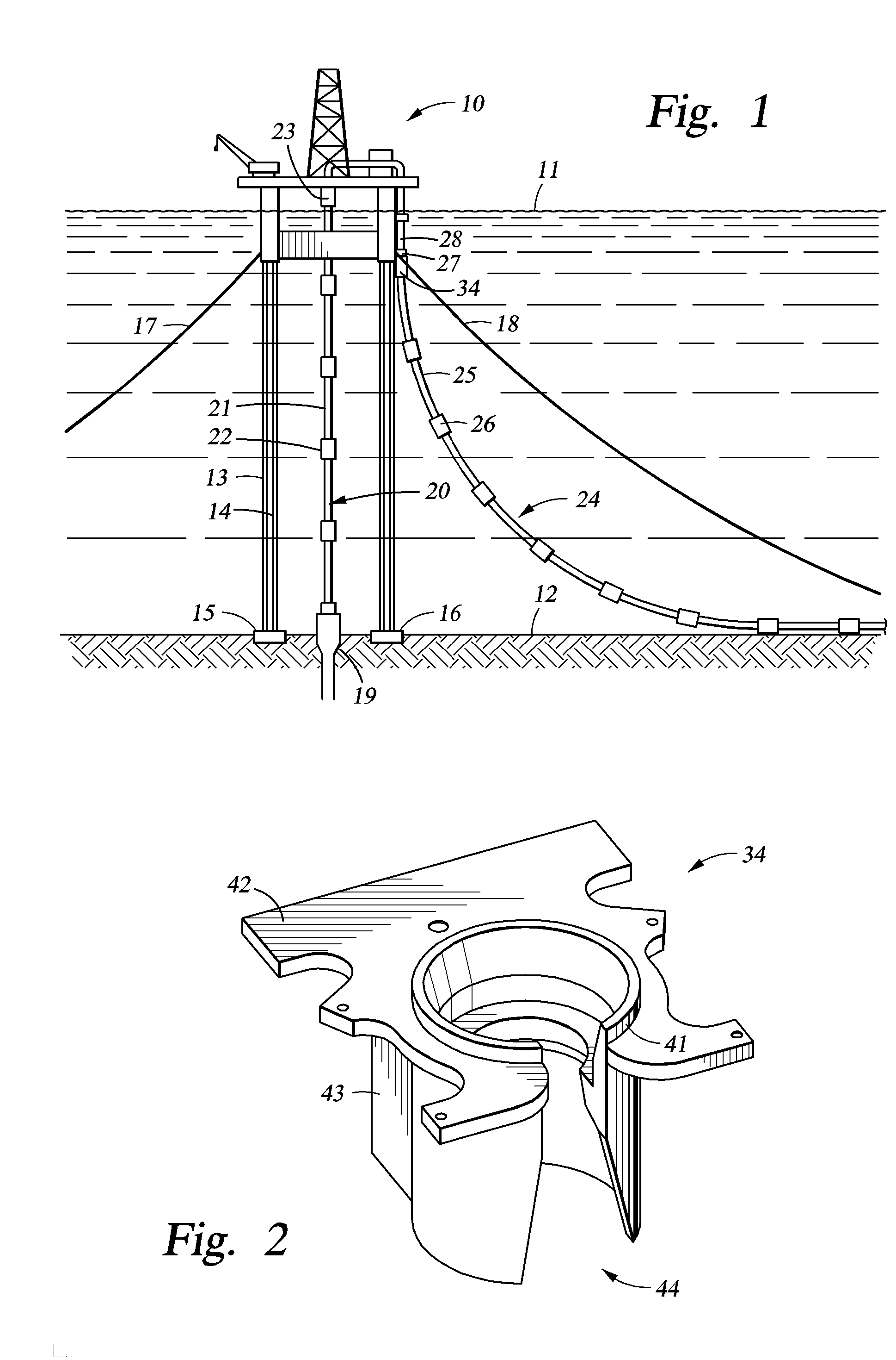
[0029]With reference to FIG. 1, there is shown an offshore drilling and production vessel generally designated 10 floating on a water surface 11. The floating vessel in particular is a tension leg platform (TLP) secured to the seabed 12 by means of tendons 13, 14 and foundation templates 15, 16. Although not visible in FIG. 1, there is a set of tendons depending from each of four corners of the TLP platform 10 to a respective one of four foundation templates 15, 16. In addition, each of the four lower corners of the TLP platform 10 is secured by a respective lateral mooring line 17, 18 used to move the platform laterally and to resist lateral storm loadings.

[0030]For conveying drilling fluids and a drill string from the TLP to a well bore 19 in the seabed 12, and for removing hydrocarbons from the well when drilling has been completed, a production riser generally designated 20 extends from the well bore 19 up to the TLP 10. The riser 20 consists of a number of rigid pipe sections 2...


PUM


Abstract

A flexible joint has an extension mounted to a housing for relative angular displacement. Two or more annular elastomeric flex elements are stacked in a co-axial fashion and joined mechanically to mount the extension to the housing so that the flex elements react in parallel to angular and axial displacements of the extension with respect to the housing so that tensile load upon the extension places each of the flex elements in compression to split and share the tensile load among the flex elements in proportion to their relative axial stiffnesses. Therefore, for a given housing size or footprint, the overall load capacity is increased, and the lifetime of the flexible joint is increased for a given load capacity. The flex elements may have a common center of rotation, and the flex elements may be disposed either on the same side of the center of rotation or on opposite sides.

Description

FIELD OF THE INVENTION [0001]The present invention relates to a flexible joint having an extension extending from a housing, and more than one annular elastomeric flex element for mounting the extension to the housing for permitting angular displacement of the extension with respect to the housing.BACKGROUND OF THE INVENTION [0002]Flexible joints having an annular elastomeric flex element mounting an extension to a housing are used for reducing motion-induced stresses between floating offshore facilities and risers and tendons depending from the floating offshore facilities. Typically the flex element consists of alternating spherical shims of metal, or other stiff material, and layers of elastomeric material. Such a flex element is capable of providing a free angular displacement of about ±15 degrees or more while supporting an axial tension proportional to the size of the flex element. Typically the size of the flex element has been selected to handle the desired load upon the ris...

Claims


Application Information

Patent Timeline
IPC IPC(8): F16L27/04
CPCF16L27/103E21B17/085
Inventor GUTIERREZ-LEMINI, DANTONPOTTORFF, TODD M.PEPPEL, GEORGE W.PATRICK, JAMES G.SPICER, CARL C.PEREIRA, JESNER H.CRUSE, GREGORY P.
Owner WELLS FARGO BANK NAT ASSOC
Why Eureka
Try Eureka