Power harvesting scheme based on piezoelectricity and nonlinear deflections

a piezoelectricity and nonlinear deflection technology, applied in the field of energy harvesting devices, can solve the problems of limiting the energy harvesting level, and affecting the efficiency of power harvesting

Inactive Publication Date: 2009-08-27
YALE UNIV
View PDF14 Cites 33 Cited by
  • Summary
  • Abstract
  • Description
  • Claims
  • Application Information

AI Technical Summary

Benefits of technology

[0025]It is an object of the present invention to provide an improved energy harvesting device that is usable to harvest energy, especially at the micro-scale level.
[0027]It is another object of the present invention to provide a mechanical structure that is capable of stretching as well as bending in response to external vibrations and that works in a non-linear deflection regime.

Problems solved by technology

One of the advantages of electromagnetic mechanisms is that no voltage source is needed to get the process going; however, a disadvantage is that the output voltage is limited to about 0.1-0.2 volts.
Electrostatic mechanisms have the advantage of being easier to integrate into Microsystems, but disadvantages resulting from the low breakdown voltage between the capacitor plates typically limit the energy levels harvested.
On the other hand, if the plates are too close together or if the voltage gets too high, air will breakdown and temporarily conduct, resulting in the loss of the charge that was stored in the capacitor.
However, a disadvantage is that conventional piezoelectric mechanisms can be somewhat difficult to integrate into microsystems.
This typically requires large nonlinear deflections.
However, when the input acceleration is far beyond the design specifications, such as when the device is unintentionally dropped on a hard surface, the acceleration of the proof mass may be several thousand times the gravitational acceleration (g), resulting in a very large deflection amplitude that bends the tethers in a nonlinear fashion.
Normally, this can cause enormous stress concentration on the ends of the tether, and structural failure of the device may result.
Even if the cantilever beam structure undergoes stretching in large magnitude deflections, the resulting large stresses are still localized to its base.
However, typical device sizes that can achieve microWatts of energy are on the order of centimeters, and scaling these devices to smaller sizes reduces the power harvested accordingly.
The suspended masses used in these systems are large, bulky and do not contribute to the physical process of voltage generation besides providing a large mass.
Unfortunately, the ambient vibrations present at these high frequencies are miniscule, and the resonant approach ensures that these devices are completely custom suited for only a very narrow range of applications.

Method used


Image

  • Power harvesting scheme based on piezoelectricity and nonlinear deflections
  • Power harvesting scheme based on piezoelectricity and nonlinear deflections
  • Power harvesting scheme based on piezoelectricity and nonlinear deflections

Examples


Embodiment Construction

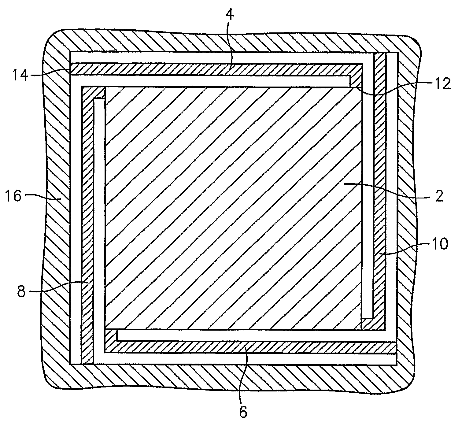
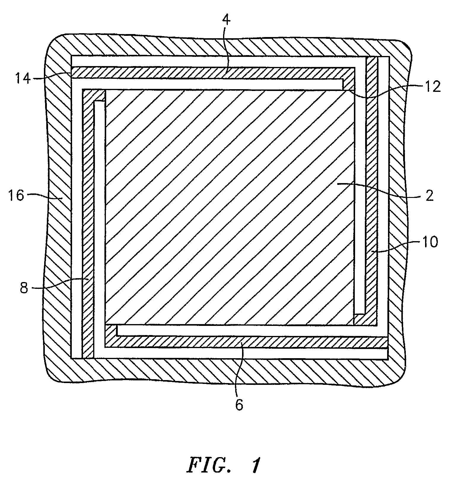
[0045]The present invention encompasses a micro-scale piezoelectric power harvesting device, similar in design to MEMS piezoelectric accelerometers. A mass is suspended by thin flexural beams from a reference (such as a frame). The base of the frame may be couplable or contactable with or is otherwise in an environment that has ambient vibrations (e.g., the wall of a building, an engine or a motor, inside of a car tire, etc.). As the frame oscillates, the mechanical vibrations are transferred to the suspended mass. In the preferred embodiment, the beams have piezoelectric material on their surfaces. As the beams flex, the piezoelectric material converts oscillatory mechanical stress into oscillatory electric voltages. If a storage capacitor is used to collect the electrical charge, electrical energy can be extracted from the mechanical oscillations. This energy can then be used to power integrated sensors or transmitters, or the like, depending on the target application.

[0046]The pr...


PUM


Abstract

An energy harvesting device and a method of using the energy harvesting device to generate an electrical charge are described. The energy harvesting device comprises a mass and at least two tethers, at least one of which comprises a piezoelectric material that is mechanically stressable upon deflection of the at least two tethers. Each of the tethers comprises a first end coupled to the mass and a second end coupled to a reference structure, and the tethers are arranged about the mass such that the mass is moveable within a straightline path relative to the reference. The movement of the mass causes the deflection of the tethers, resulting in the generation of an electric charge. The device is preferably operable at the microscale.

Description

CROSS REFERENCE TO RELATED APPLICATIONS[0001]This application claims the benefit of U.S. Provisional Application No. 60 / 665,226, filed Mar. 24, 2005, the subject matter of which is herein incorporated by reference in its entirety.FIELD OF THE INVENTION[0002]The present invention is directed to an energy harvesting device.BACKGROUND OF THE INVENTION[0003]Energy harvesting involves the use of ambient energy sources to produce power. Using ambient energy sources to produce power may allow the use of self-powering circuits and enables the use of low power sensing monitoring, communication, computation, actuation and control applications. Harvesting energy from ambient energy sources is especially useful for long-term remote applications that would otherwise require multiple battery replacements. Mechanical vibration is a potential power source that is converted into electrical energy through microelectromechanical systems (MEMS) technology. Ambient vibration energy sources include, for ...

Claims


Application Information

Patent Timeline
Patent Type & Authority Applications(United States)
IPC IPC(8): H02N2/18H01L41/04F03G7/08H01L41/22H01L41/311
CPCB60C23/0411H02N2/186H01L41/1136H10N30/306
Inventor KOSER, HURZHANG, NIAN
Owner YALE UNIV
Why Eureka
Try Eureka