Object Detection
a technology for objects and detection methods, applied in the field of objects detection, can solve problems such as inability to assign a distinct pulse train to each individual
- Summary
- Abstract
- Description
- Claims
- Application Information
AI Technical Summary
Benefits of technology
Problems solved by technology
Method used
Image
Examples
example 1
[0070]Assume that the number J of clock pulses occurring in a single cycle is equal to 30, and that the minimum and maximum values of the interpulse interval are, respectively, Tmin=40 ns and Tmax=185 ns. Because each value of the interpulse interval is to occur exactly once, the histogram of the interval values will be of the form shown in FIG. 6. As seen, the durations of the interpulse intervals increase in steps of 5 ns.
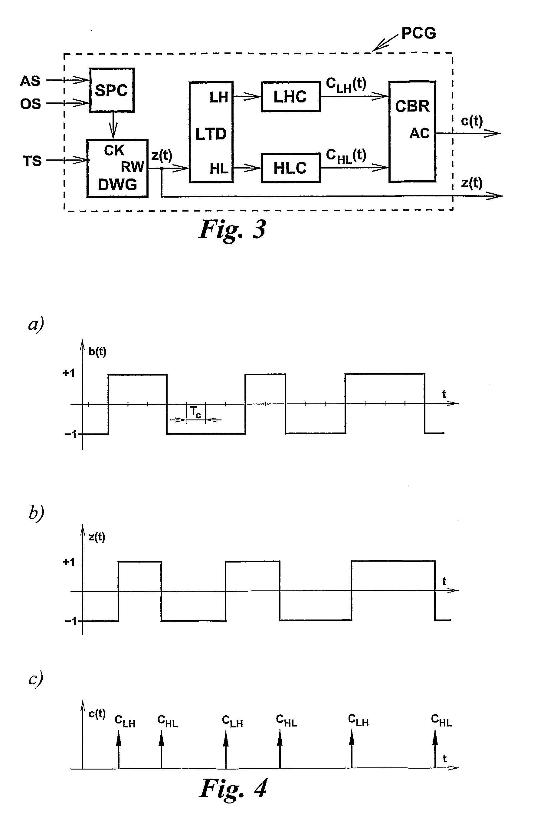
[0071]In this case, the average value of the interpulse interval is equal to 112.5 ns, but may easily be varied, e.g. by changing the minimum value Tmin of the interpulse interval. This can be accomplished by applying a suitable signal to input AS of the spread-period clock generator.
[0072]While the order in which different interpulse interval values occur cannot change the histogram shape, it does make the resulting series of antithetic clicks statistically distinct, especially when the permutation of interval values is carried out repeatedly, e.g., on a cycle-t...
example
[0082]Assume that K=6, −NV=−4 and Tc=5 ns.
[0083]Therefore, Tmin=(NV)Tc=20 ns, whereas Tmax=Tmin+(2K−1)Tc=215 ns.
[0084]In a general case, the transition-matrix circuit TMX has M inputs and K outputs, where M≧K. However, in the simplest arrangement, M=K, and the TMX has K inputs, I1, I2, . . . , IK and K outputs, O1, O2, . . . , OK; hence the PRBS generator has K parallel outputs driving inputs I1, I2, . . . , IK. The operation of the TMX can be explained by way of an example shown in FIG. 17. The pattern of K, K=8, dots in a K×K matrix corresponds to input-output connections realized by the TMX. Therefore, in this case, O1=I7, O2=I1, . . . , O7=I2 and O8=I5. Obviously, each column and each row of the matrix must contain exactly one dot.
[0085]Although many different dot patterns can be devised for this application, it may be advantageous to utilize a dot pattern belonging to a class of patterns referred to as ‘K non-attacking Queens’, such as the dot pattern shown in FIG. 17. Also, ot...
example 2
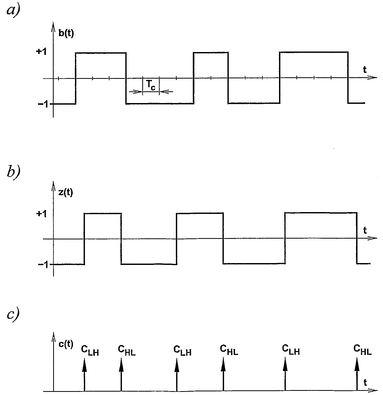
[0118]Assume that the template binary waveform b(t) is a ‘maximal-length’ pseudorandom binary signal generated by a seven-stage shift register as shown in FIG. 9. Therefore, the duration of each prbs period will be equal to 127 clock interpulse intervals.
[0119]Assume also that the prbs generator is driven by a spread-period clock generator that operates cyclically, and its characteristics are the same as those discussed in Example 1, namely:[0120]1. the number K of clock pulses occurring in a single cycle is equal to 30;[0121]2. the minimum and maximum values of the interpulse interval are, respectively, Tmin=40 ns and Tmax=185 ns, with the average value of 112.5 ns,[0122]3. the duration of the interpulse intervals always increases by a step of 5 ns.
[0123]When clock pulses with the above characteristics drive the prbs generator, the output compound binary waveform will repeat itself every 127×30=3810 clock interpulse intervals, or 3810×112.5 ns≈429 μs (this is because 127 and 30 are...
PUM
 Abstract
Description
Claims
Application Information
 - R&D
- Intellectual Property
- Life Sciences
- Materials
- Tech Scout
- Unparalleled Data Quality
- Higher Quality Content
- 60% Fewer Hallucinations
Browse by: Latest US Patents, China's latest patents, Technical Efficacy Thesaurus, Application Domain, Technology Topic, Popular Technical Reports.
© 2025 PatSnap. All rights reserved.Legal|Privacy policy|Modern Slavery Act Transparency Statement|Sitemap|About US| Contact US: help@patsnap.com


