Liquid ejecting head, method of manufacturing the same, and liquid ejecting apparatus

a technology of liquid ejecting head and liquid ejecting apparatus, which is applied in the direction of metal-working apparatus, printing, writing implements, etc., can solve the problems of inability to reduce the interval between adjacent ink supply needles, inability to discharge, and inability to remov

Active Publication Date: 2009-08-27
SEIKO EPSON CORP
View PDF32 Cites 14 Cited by
  • Summary
  • Abstract
  • Description
  • Claims
  • Application Information

AI Technical Summary

Benefits of technology

[0011]An advantage of some aspects of the invention is that it provides a liquid ejecting head that is able to prevent leakage of liquid, a method of manufacturing the liquid ejecting head, and a liquid ejecting apparatus.
[0012]An aspect of the invention provides a liquid ejecting head. The liquid ejecting head has an nozzle opening for ejecting liquid supplied from a liquid reservoir unit, which stores the liquid, through a liquid supply passage. The liquid ejecting head includes: a first supply member and a second supply member, each of which has the liquid supply passage formed therein; a filter that is held between the first supply member and the second supply member in correspondence with the liquid supply passage; a thermally welded portion that is welded to the filter so that the first supply member melts and soaks into the filter in a region that surrounds the liquid supply passage; a bonded portion at which the second supply member is bonded to the filter by the thermally welded portion; and a bonding resin that is formed by being poured into an outer region between the first supply member and the second supply member and outside the thermally welded portion and bonded portion with respect to the liquid supply passage. According to the above aspect, the thermally welded portion, the bonded portion and the bonding resin fix and integrate the first supply member, the filter and the second supply member. Thus, it is possible to isolate the liquid supply passage without reducing the effective area of the filter. In addition, even when a filter that extends over a plurality of flow passages is used, liquid that flows through each of the plurality of flow passages is not mixed with each other through the filter, so the size of the head may be reduced. In addition, it is not necessary to reduce the effective area of the filter for reducing the size of the head. This prevents an increase in dynamic pressure and, therefore, it is not necessary to increase a driving voltage at which a pressure generating device, such as a piezoelectric element or a heater element, is driven. Furthermore, the area of the peripheral portion of the filter is minimized and then the outer peripheral end surfaces of the filter is covered with the outer portion. In addition, the thermally welded portion reliably prevents a gap from being formed between a supply element and a filter fitting member, so it is possible to reliably prevent leakage of liquid through a gap.
[0013]Here, the bonding resin may be formed in a region outside the bonded portion and facing the thermally welded portion. With this configuration, it is possible to fix and integrate the first supply member, the filter and the second supply member in a state where the adjacent liquid flow passages are further reliably isolated from each other.
[0014]In addition, the thermally welded portion may be present all around a region of the filter, which surrounds the liquid supply passage, an outer portion may be further provided continuously to the bonding resin in the outer region all around the first supply member and the second supply member, and the first supply member and the second supply member may additionally be bonded by the outer portion. With this configuration, integration of the first supply member with the second supply member is further enhanced by the outer portion. Thus, it is possible to further reliably prevent leakage between the adjacent liquid supply passages.
[0017]Furthermore, another aspect of the invention provides a liquid ejecting apparatus that includes the liquid ejecting head according to the above aspect. With this configuration, it is possible to implement a small, low-cost liquid ejecting apparatus.
[0018]Further another aspect of the invention provides a method of manufacturing a liquid ejecting head having a nozzle opening for ejecting liquid supplied from a liquid reservoir unit, which stores the liquid, through a liquid supply passage formed at least in a first supply member and a second supply member. The method includes: thermally welding a filter with the first supply member through a thermally welded portion by melting a thermally welded region of the first supply member, which is provided around the liquid supply passage; arranging the second supply member so as to face and contact the thermally welded portion of the first supply member to which the filter is welded; and bonding the first supply member with the arranged second supply member. According to the above aspect, the second supply member is fixedly bonded and integrated with the filter through the thermally welded portion that integrates the first supply member with the filter. Thus, it is possible to achieve the integration in a state where the filters are completely isolated without reducing the effective area and, therefore, the size of the head may be reduced. In addition, it is not necessary to reduce the effective area of the filter for reducing the size of the head. This prevents an increase in dynamic pressure and, therefore, it is not necessary to increase a driving voltage at which a pressure generating device, such as a piezoelectric element or a heater element, is driven. Furthermore, the area of the peripheral portion of the filter is minimized and then the outer peripheral end surfaces of the filter is covered with the thermally welded portion. In addition, the thermally welded portion reliably prevents a gap from being formed between a supply element and a filter fitting member, so it is possible to reliably prevent leakage of liquid through a gap.

Problems solved by technology

In the above ink jet recording head, when bubbles that are present in ink contained in the ink cartridge or bubbles trapped into ink when the ink cartridge is attached or detached are supplied to the head element, the bubbles problematically cause defective discharge, such as dot omission.
Thus, an interval between the adjacent ink supply needles cannot be reduced and, therefore, the size of a head problematically increases.
This problematically requires an increase in driving voltage for driving a pressure generating device, such as a piezoelectric element or a heater element.
In addition, when the ink supply needle is fixed to the supply member by means of thermal welding, a gap may be formed therebetween.
Thus, ink problematically leaks through the gap.
Note that the above problems are not only present in the ink jet recording head but also similarly present in a liquid ejecting head that ejects liquid other than ink.

Method used


Image

  • Liquid ejecting head, method of manufacturing the same, and liquid ejecting apparatus
  • Liquid ejecting head, method of manufacturing the same, and liquid ejecting apparatus
  • Liquid ejecting head, method of manufacturing the same, and liquid ejecting apparatus

Examples


first embodiment

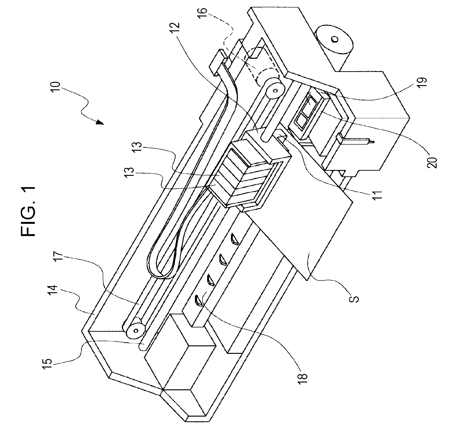
[0034]FIG. 1 is a schematic perspective view of an ink jet recording apparatus, which is an example of a liquid ejecting apparatus, according to a first embodiment of the invention. As shown in FIG. 1, the ink jet recording apparatus 10 according to the present embodiment is formed so that an ink jet recording head 11 (hereinafter, also referred to as recording head), which is an example of a liquid ejecting head that discharges ink droplets, is fixed to a carriage 12, ink cartridges 13, which are liquid reservoir portions, are detachably fixed to the recording head 11, and a plurality of different color inks, such as black (B), light black (LB), cyan (C), magenta (M), yellow (Y), and the like, are stored in the ink cartridges 13.

[0035]The carriage 12, on which the recording head 11 is mounted, is axially movably provided on a carriage shaft 15 connected to an apparatus body 14. Then, driving force of a drive motor 16 is transmitted to the carriage 12 through a plurality of gears (n...

second embodiment

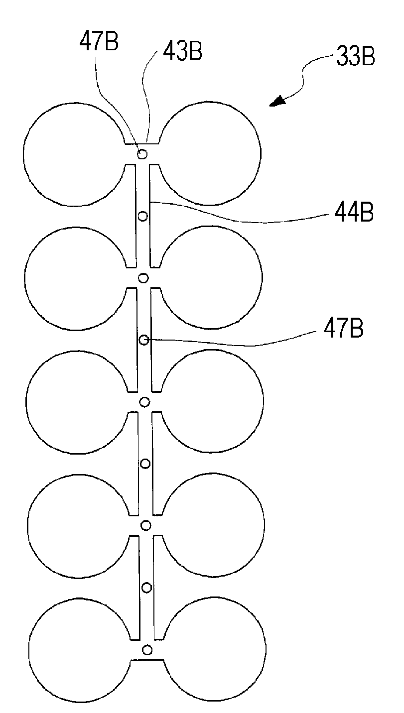
[0076]FIG. 11 is a cross-sectional view of a supply member according to a second embodiment. The supply member 30A of the present embodiment is similar to that of the first embodiment except that the outer portion is formed to extend continuously to the upper surfaces of the thermally welded portions. Like reference numerals denote like components to those of the first embodiment, and the description thereof will not be repeated.

[0077]As shown in the drawing, the supply needles 32A contact only in regions inside the thermally welded portions 34A of the filters 33A and supply member elements 31A to form the bonded portions 38A, the bonding resins 49A of the outer portion 39A are formed to enter into regions outside the upper surfaces of the thermally welded portions 34A, and then the thermally welded portions 34A, the bonded portions 38A and the bonding resins 49A are integrated. That is, the filter holding portions 42A of the supply needles 32A are formed to be smaller than the filt...


PUM

PropertyMeasurementUnit
areaaaaaaaaaaa
sizeaaaaaaaaaa
dynamic pressureaaaaaaaaaa

Abstract

A liquid ejecting head includes: a first supply member and a second supply member, each of which has a liquid supply passage formed therein; a filter that is held between the first supply member and the second supply member in correspondence with the liquid supply passage; a thermally welded portion that is welded to the filter so that the first supply member melts and soaks into the filter in a region that surrounds the liquid supply passage; a bonded portion at which the second supply member is bonded to the filter by the thermally welded portion; and a bonding resin that is formed by being poured into an outer region between the first supply member and the second supply member and outside the thermally welded portion and bonded portion with respect to the liquid supply passage.

Description

BACKGROUND[0001]1. Technical Field[0002]The invention relates to a liquid ejecting head, a method of manufacturing the same, and a liquid ejecting apparatus provided with the liquid ejecting head and, more particularly, to an ink jet recording head that discharges ink as liquid, a method of manufacturing the same, and an ink jet recording apparatus.[0003]2. Related Art[0004]In an ink jet recording head, which is a typical liquid ejecting head, generally, ink is supplied from an ink cartridge, which is a liquid reservoir portion and filled with ink, to a head element through an ink flow passage, which is formed in a supply member, such as an ink supply needle, which is an ink supply element and detachably inserted into the ink cartridge, and a cartridge case in which the ink cartridge is held, and the ink supplied to the head element is discharged from a nozzle by driving a pressure generating device, such as a piezoelectric element, provided for the head element.[0005]In the above i...

Claims


Application Information

Patent Timeline
Patent Type & Authority Applications(United States)
IPC IPC(8): B41J2/175B23P17/00
CPCY10T29/49401B41J2/17563
Inventor OWAKI, HIROSHIGEKAMIKURA, HIROYUKI
Owner SEIKO EPSON CORP
Why Eureka
Try Eureka