Imaging apparatus

Inactive Publication Date: 2009-08-27
SONY CORP
View PDF2 Cites 46 Cited by
  • Summary
  • Abstract
  • Description
  • Claims
  • Application Information

AI Technical Summary

Benefits of technology

[0031]According to the invention of Claim 6, a parameter that controls the exposure start operation through the electronic focal plane shutter function can be changed by using at least one of a shutter speed, a focal length, an aperture value, and information about the position of the exit pupil. Accordingly, for example, the shutter speed of the electronic focal plane shutter can be changed (control for increasing or decreasing the curtain speed can be performed) on the basis of at least one of a shutter speed, a focal length, an aperture value, and information about the position of the exit pupil. Therefore, at a low shutter speed in which the electronic focal plane shutter is used, in accordance with the performance of the photo-taking lens, for example, as the focal length is decreased and the F no. is decreased or as the position of the exit pupil is closer to the exposure surface, the shutter speed of the electronic focal plane shutter can be increased. As a result, the occurrence of unevenness of exposure due to the edge darkening phenomenon of a light ray at a low shutter speed can be prevented (or reduced).
[0032]According to the invention of Claim 7, the exposure start operation is performed by one of focal plane shutters realized by the electronic focal plane shutter function and the mechanical focal plane shutter after a predetermined period of time has elapsed since the operation of the movable mirror was completed. Accordingly, a user can capture an image (start an exposure operation) at the same release timing, regardless of whether the e

Problems solved by technology

In such an image pickup apparatus, vibration of the mechanical focal plane shutter may occur.
This vibration causes a negative impact on the image capturing (exposure) operation.
This vibration causes vibration of the image sensor, and therefore, an image on the image sensor is blurred during the exposure time Δt.
Due to the difference in speed between the curtains, especially during an operation with high SS (shutter speed) which causes a slit exposure, stable exposure cannot be obtained, that is, unevenness of exposure occurs.
Furthermore, since the position of the first curtain is separated from the position

Method used


Image

  • Imaging apparatus
  • Imaging apparatus
  • Imaging apparatus

Examples


Embodiment Construction

[0063]Embodiments of the present invention are described below with reference to the accompanying drawings.

Description of Camera Structure

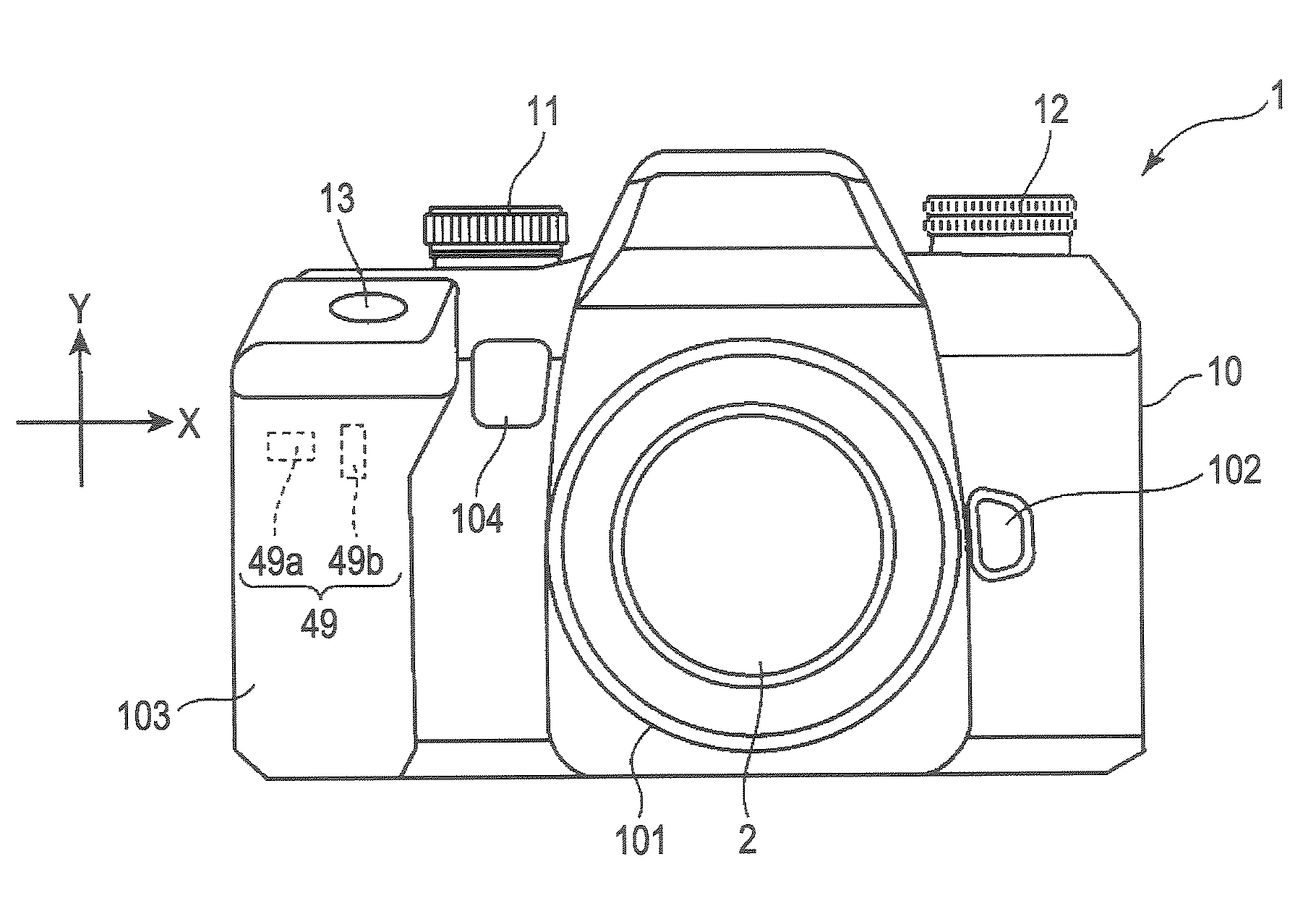
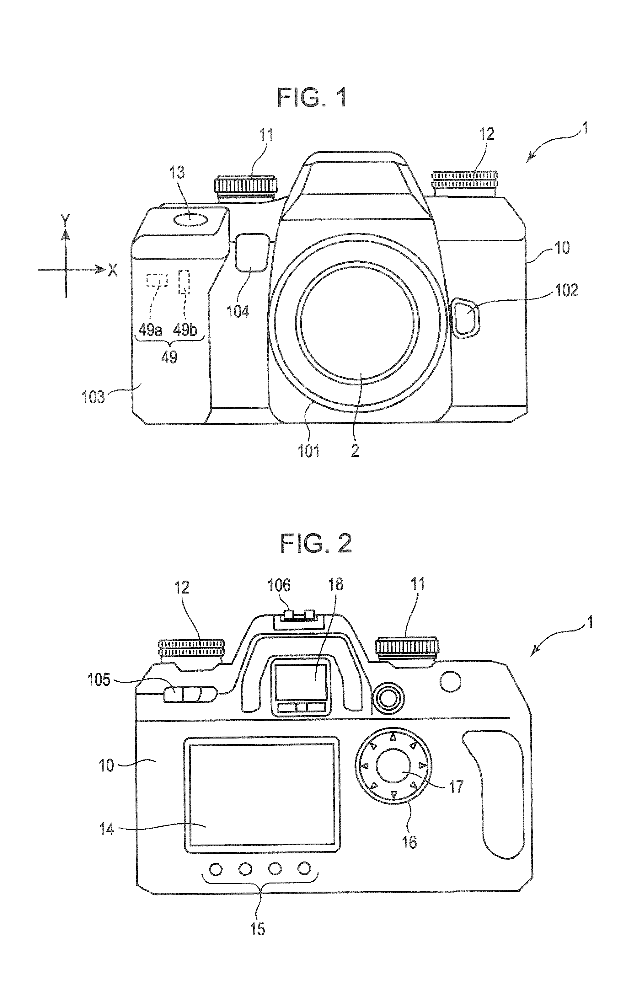
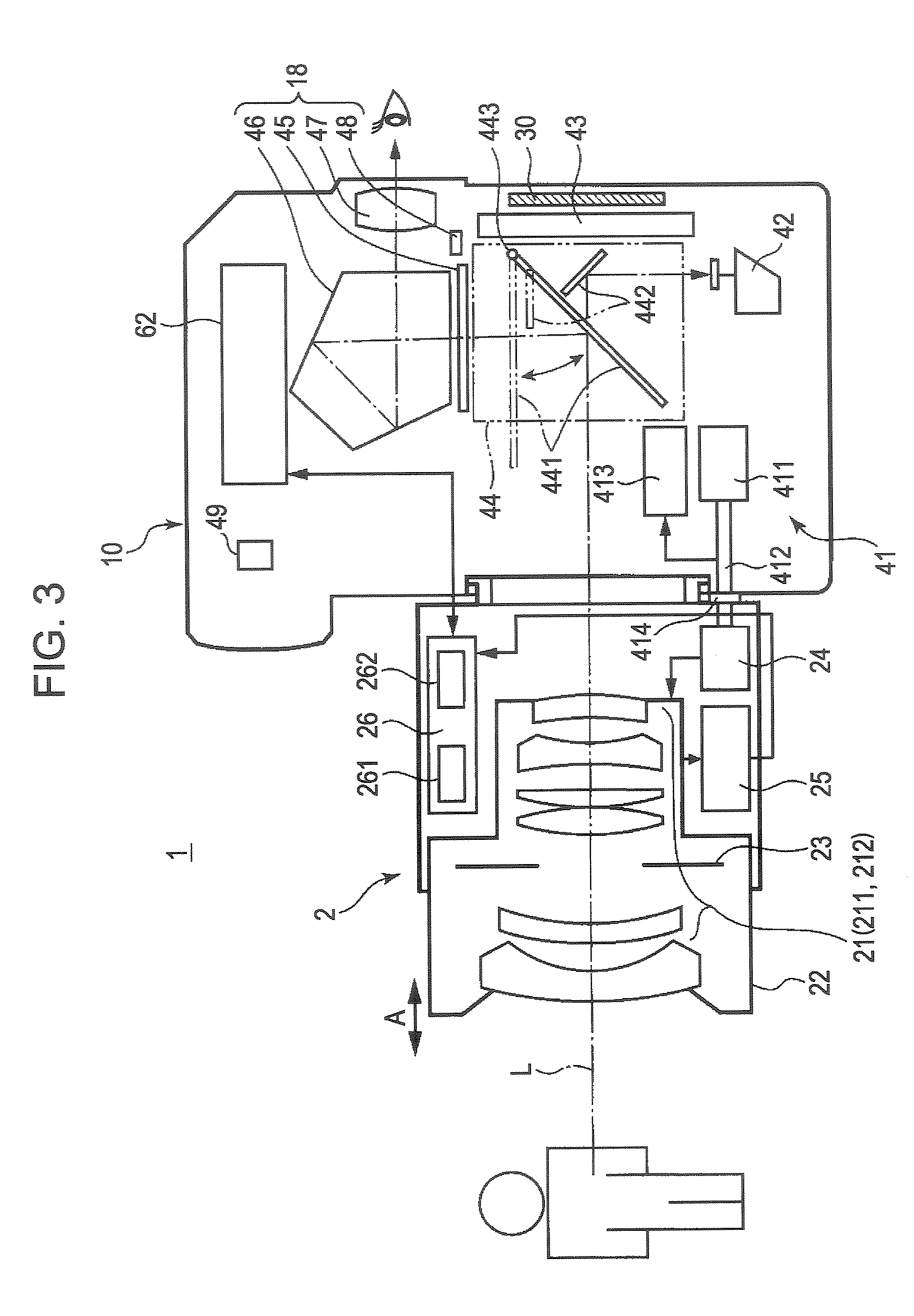
[0064]FIGS. 1 and 2 illustrate the external structure of a digital camera (image pickup apparatus) 1 including an image pickup unit according to the present invention. FIG. 1 is a front view of the digital camera 1. FIG. 2 illustrates a back view of the digital camera 1. FIG. 3 is a cross-sectional view illustrating the internal structure of the digital camera 1. As shown in FIG. 1, the digital camera 1 is a digital single-lens reflex camera including a camera body 10 and a photo-taking lens (interchangeable lens) 2 mounted on the camera body 10 at substantially the front center thereof.

[0065]As shown in FIG. 1, the camera body 10 includes the following on the front surface: a mounting unit 101 on which the photo-taking lens 2 is mounted, a lens interchanging button 102 disposed on the right side of the mounting unit 101, a grip 103 that extends f...


PUM


Abstract

Problems, such as unevenness of exposure, caused by the difference in speed between a first curtain and a second curtain and a positional shift between the curtains (the occurrence of an edge darkening phenomenon) can be prevented. In addition, power consumption is reduced. When the shutter speed is set to be low by exposure control means, the exposure start operation is performed using an electronic focal plane shutter function of an image sensor (an electronic focal plane shutter is used for the first curtain), and an exposure end operation is performed by a mechanical focal plane shutter. In contrast, when the shutter speed is set to be high by the exposure control means, the exposure start operation and the exposure end operation are performed using the mechanical focal plane shutter (the mechanical focal plane shutter is used for the first curtain).

Description

TECHNICAL FIELD[0001]The present invention relates to an image pickup unit and an image pickup apparatus including a MOS image sensor and, in particular, to an image pickup unit and an image pickup apparatus that use an electronic focal plane shutter for a first curtain and a mechanical focal plane shutter for a second curtain.BACKGROUND ART[0002]MOS (metal oxide semiconductor) based X-Y scanning image sensors can provide a high-speed readout operation of a pixel signal, low power consumption, and high integration as compared with CCD (charged coupled Device) based image sensors. Since MOS-based X-Y scanning image sensors satisfy the requirement for image pickup apparatuses in terms of the size and performance thereof, MOS-based X-Y scanning image sensors are widely used for image sensors mounted in image pickup apparatuses. In addition, MOS-based X-Y scanning image sensors can provide a function of performing a random scan that enables readout of an electrical charge from any one s...

Claims


Application Information

Patent Timeline
IPC IPC(8): H04N5/228H04N5/335H04N5/232H04N5/235G03B7/093G03B9/36G03B17/14H04N5/225H04N101/00
CPCG03B7/093G03B9/36G03B17/14H04N2101/00H04N5/2353H04N5/3532H04N5/2254H04N23/55H04N23/73H04N25/531G03B9/08H04N23/75
Inventor KIDO, TOSHIHITO
Owner SONY CORP
Why Eureka
Try Eureka