Liquid crystal display panel and method for manufacturing the same

a technology of liquid crystal display panel and liquid crystal display panel, which is applied in the direction of liquid crystal compositions, chemistry apparatus and processes, instruments, etc., can solve the problems of unfavorable uniformity, bad contrast or mura, and unfavorable uniformity, so as to improve brightness and mura

Inactive Publication Date: 2009-08-27
AU OPTRONICS CORP
View PDF3 Cites 17 Cited by
  • Summary
  • Abstract
  • Description
  • Claims
  • Application Information

AI Technical Summary

Benefits of technology

[0016]An objective of the present invention is to improve brightness and mura by adjusting the distances between adjacent liquid crystal drops and weight thereof.
[0017]An objective of the present invention is to improve brightness and mura by adjusting the distances between adjacent liquid crystal drop patterns and weight thereof.

Problems solved by technology

However, while applying ODF, some problems occur: bad uniformity of moving or expending of the liquid crystal between the two substrates, unexpected bumps between the liquid crystal drops, undesired uniformity or density of impurities in liquid crystal, or bad contrast or mura as driving the liquid crystal display, etc.

Method used


Image

  • Liquid crystal display panel and method for manufacturing the same
  • Liquid crystal display panel and method for manufacturing the same
  • Liquid crystal display panel and method for manufacturing the same

Examples


Embodiment Construction

[0032]Reference will now be made in detail to the present preferred embodiments of the invention, examples of which are illustrated in the accompanying drawings. Wherever possible, the same reference numbers are used in the drawings and the description to refer to the same or like parts.

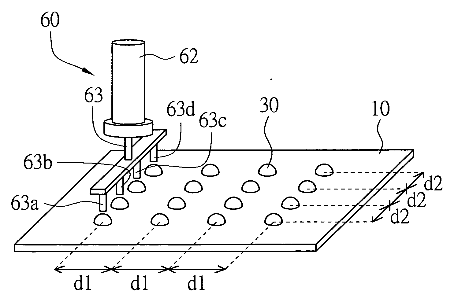
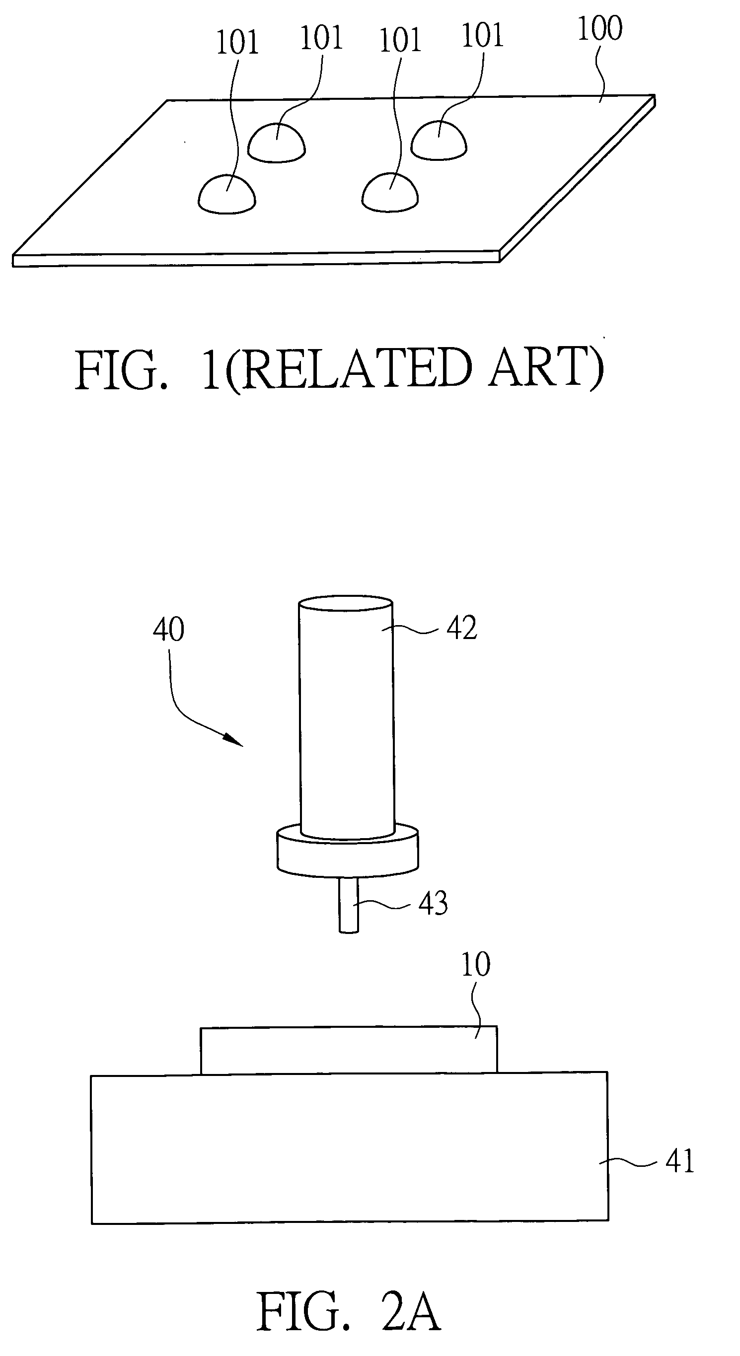
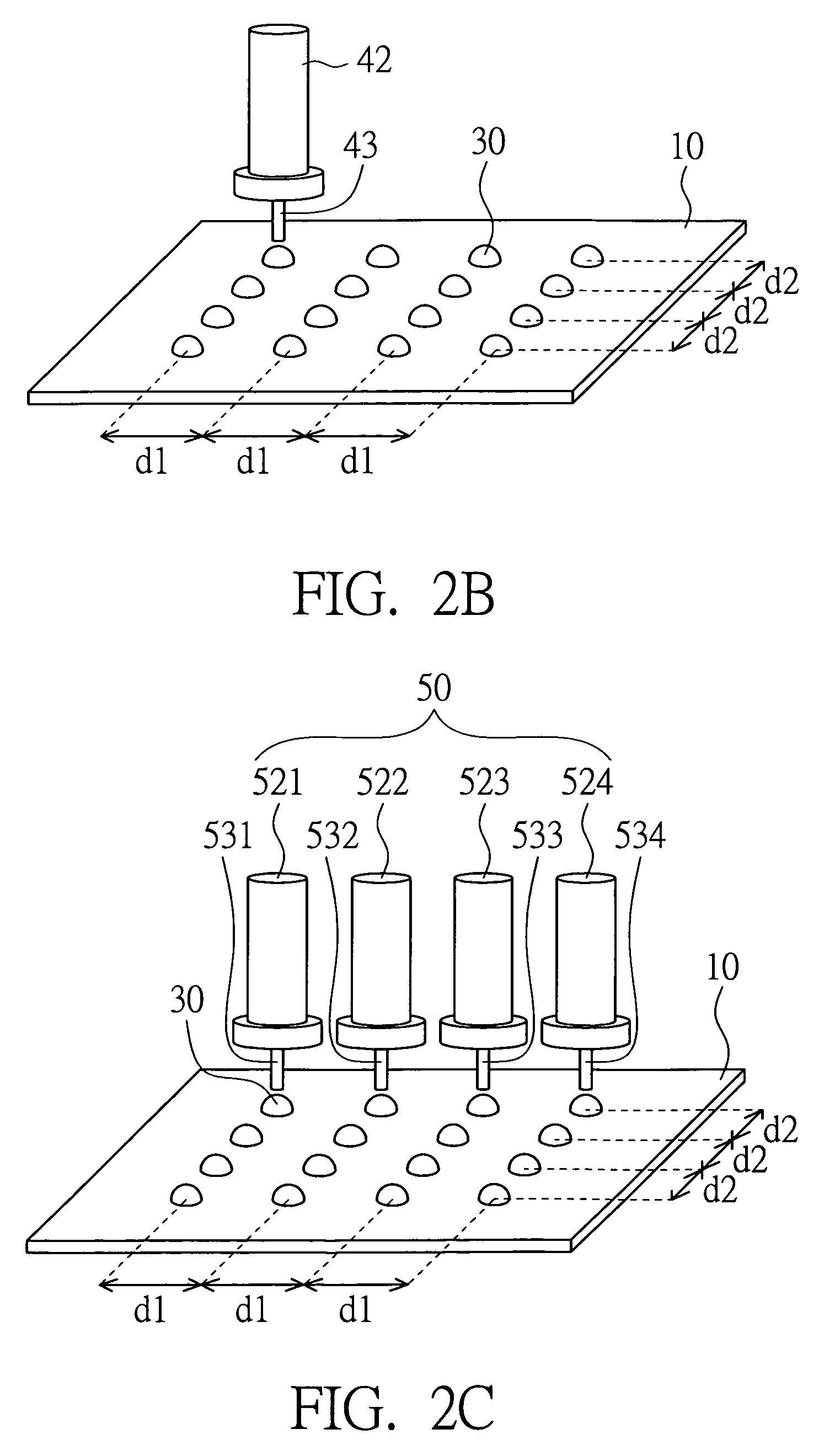
[0033]FIGS. 2A to 4 are prospective views showing one drop fill process (ODF) according to an embodiment of the present invention. As shown in FIG. 2A, liquid crystal provider 40 includes splitter 42 and nozzle 43 connected with the splitter 42. The splitter 42 can store or temporarily contain the liquid crystal. Liquid crystal drops are provided from the nozzle 43. First substrate 1 is disposed on the plate 41. The first substrate 1 is active array substrate, color filter on array substrate or color filter substrate, for example. As shown in FIG. 2B, an ODF is conducted. Provide first substrate 10 and disposed single liquid crystal provider 40 which has single splitter 42 and single nozzle 43 above ...


PUM

PropertyMeasurementUnit
weightaaaaaaaaaa
distancesaaaaaaaaaa
moving distanceaaaaaaaaaa

Abstract

A method for manufacturing a liquid crystal display panel is provided. The method includes: providing a first substrate and a second substrate; providing a plurality of liquid crystal drops on the first substrate, wherein two adjacent liquid crystal drops in X direction is kept by a distance d1 mm, and two adjacent liquid crystal drops in Y direction is kept by a distance d2 mm, each liquid crystal drop is G mg, d1≦16.7, d2≦15.4, and G≦1; and connecting the first substrate and the second substrate so that the liquid crystal drops are sealed between the first substrate and the second substrate.

Description

[0001]This application claims the benefit of Taiwan Patent Application Serial No. 97102720, filed Jan. 24, 2008, the subject matter of which is incorporated herein by reference.BACKGROUND OF THE INVENTION[0002]1. Field of the Invention[0003]The present invention generally relates to a method for manufacturing a liquid crystal display panel, and especially relates to a method for providing liquid crystal by one drop fill process (ODF).[0004]2. Description of Related Art[0005]Liquid crystal displays are commonly used because of thin, short and low radiation. Conventional liquid crystal display includes two substrates and a liquid crystal layer disposed therebetween. A sealant is located between the substrates for combining the two substrates and sealing the liquid crystal layer. The two substrates are active array substrate and color filter substrate, respectively.[0006]In the present, methods for providing liquid crystal layer include injection and one drop fill process (ODF), etc. U...

Claims


Application Information

Patent Timeline
Patent Type & Authority Applications(United States)
IPC IPC(8): G02F1/1341G02F1/1339
CPCG02F1/1339G02F2001/13415G02F1/1341G02F1/13415
Inventor JIAN, JIA-HAUCHIU, CHIH-HOCHIANG, CHENG-JUNGHSIEH, CHUNG-CHINGCHEN, TE-SHENGSUGIURA, NORIO
Owner AU OPTRONICS CORP
Why Eureka
Try Eureka