Housing for a Computer

a computer and housing technology, applied in the field of housing for computers, can solve the problem of distributing heat sufficiently quickly, and achieve the effect of improving thermal coupling and improving cooling performan

Inactive Publication Date: 2009-08-27
HUSH TECH INVESTMENTS
View PDF21 Cites 13 Cited by
  • Summary
  • Abstract
  • Description
  • Claims
  • Application Information

AI Technical Summary

Benefits of technology

[0025]The heat sinks preferably each comprise a plurality of cooling fins to improve the cooling performance.
[0026]The one or the plurality of heat conduction conduits can preferably extend in recesses in the opposing walls to further improve the thermal coupling between the heat conduit or conduits and the opposing walls.

Problems solved by technology

As a result of the increasing performance and power consumption, measures for cooling these components are required.
When using heat sinks however, there is the problem of distributing the heat to be dissipated sufficiently rapidly to the largest possible surface of the heat sink.

Method used


Image

  • Housing for a Computer
  • Housing for a Computer
  • Housing for a Computer

Examples


Embodiment Construction

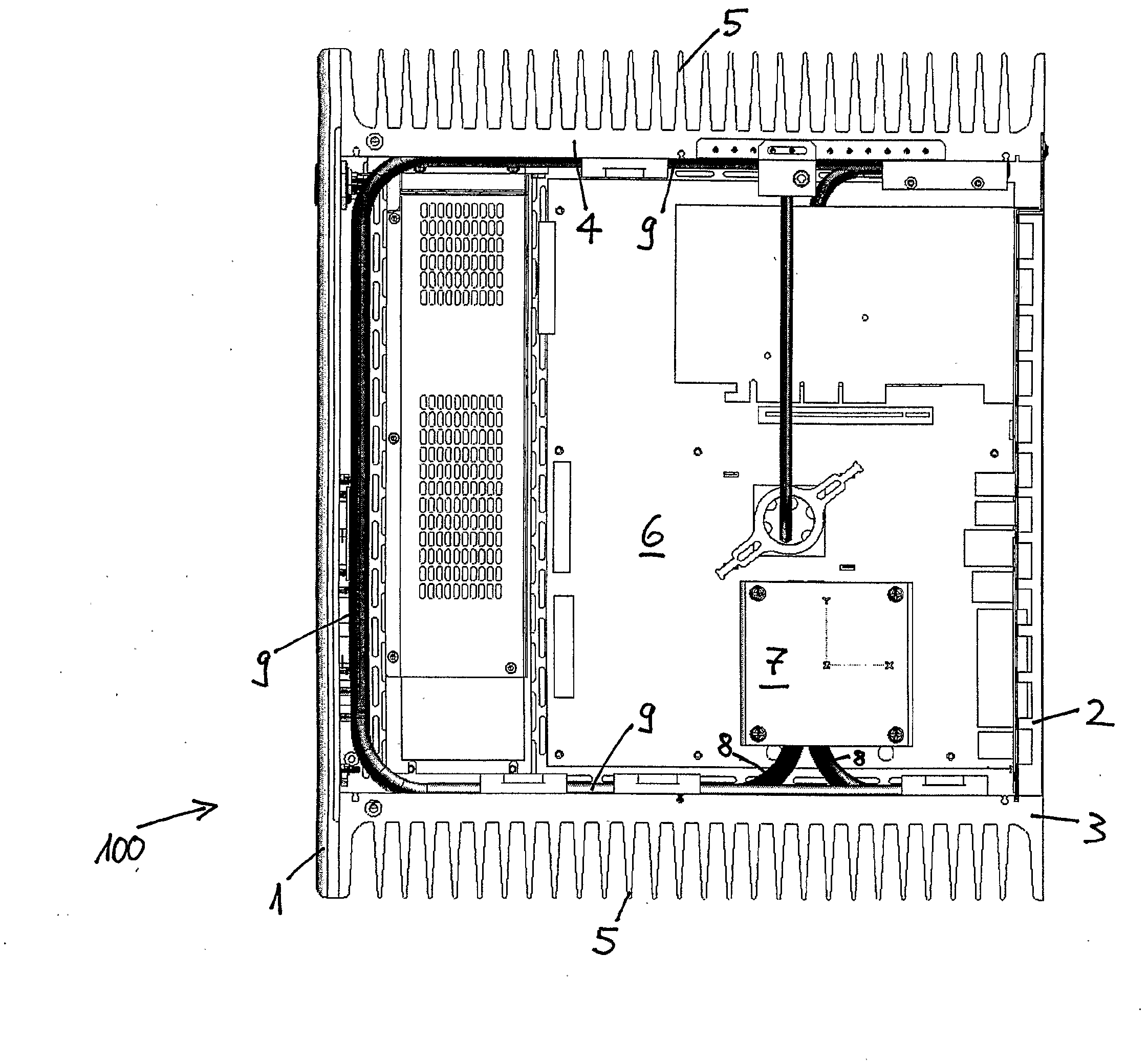
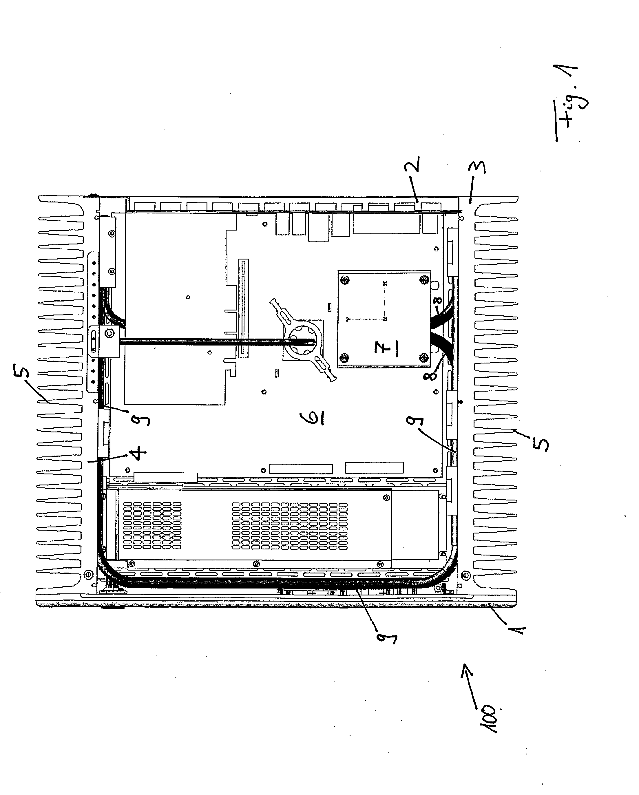
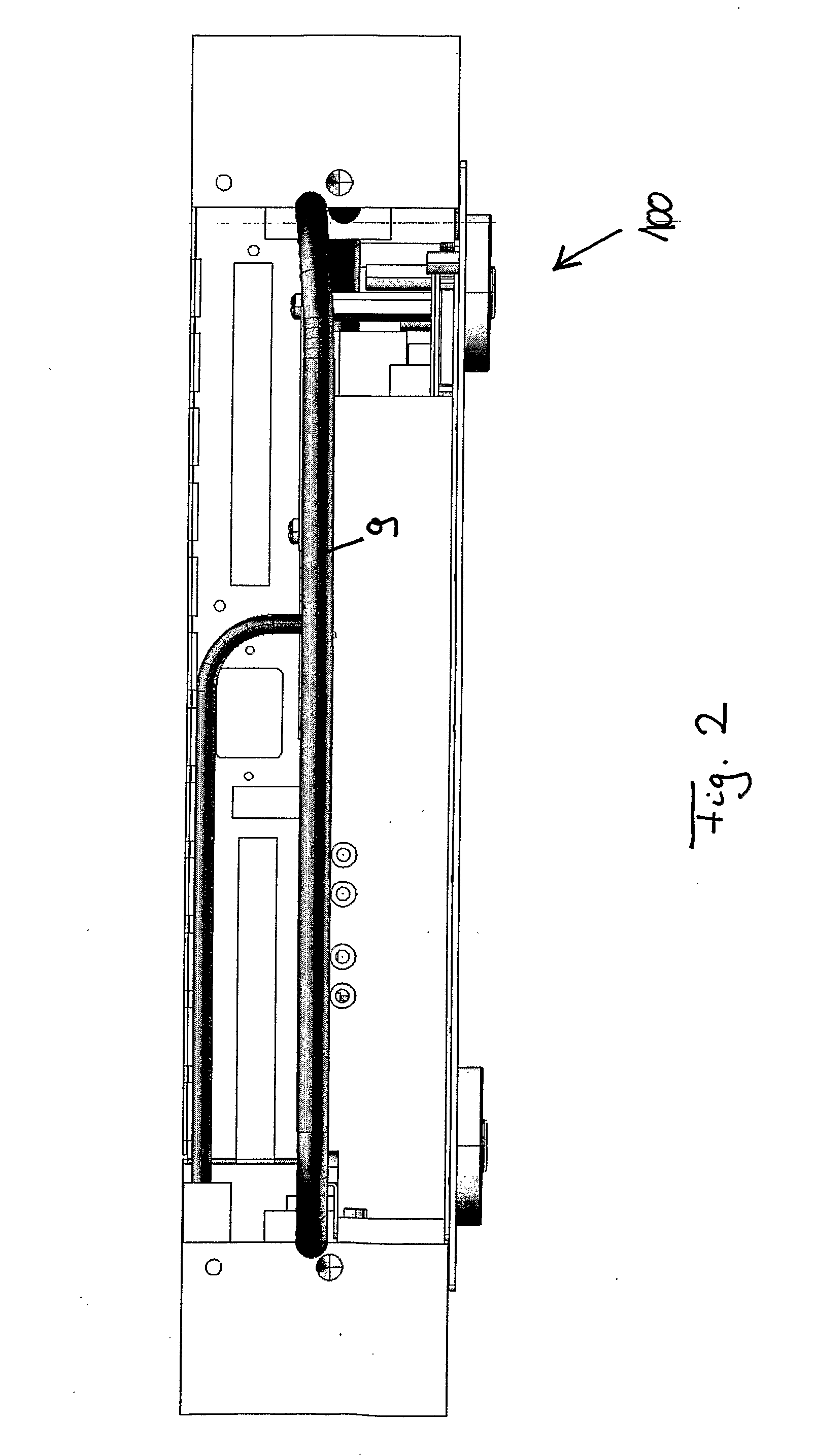
[0032]FIGS. 1 to 3 illustrate schematically an opened computer housing 100 according to one embodiment of the invention, where FIG. 1 is a plan view of the housing 100 with the cover plate removed, FIG. 2 is a front view with the front plate removed and FIG. 3 is a perspective view likewise with the cover plate removed. In all three figures, the same reference numerals are used for elements which correspond to one another.

[0033]The computer housing 100 has a front wall 1, a rear wall 2 and side walls 3 and 4 located opposite to one another. The side walls 4 comprise a plurality of cooling fins 5 and thus each form a heat sink for removing heat from the housing 100. The cooling fins extend perpendicularly to the longitudinal extension of the side walls 3, 4 and are uniformly spaced apart. The surface of the cooling fins can be corrugated for better heat removal.

[0034]The interior of the computer housing 100 contains a motherboard 6 on which a heat-generating element 7 is located. The...


PUM


Abstract

A housing for a computer or multi-media equipment or the like includes at least one heat-generating component. The housing may have a respective cooling body on opposing walls and a heat conduction conduit that is thermally coupled to the heat-generating component. The heat conduction conduit can run along both opposing walls and is thermally coupled to the cooling bodies, whereby heat from the heat-generating component can be dissipated from the housing via the heat conduction conduit and the cooling bodies. By running the heat conduction conduit along opposing walls, heat may be transferred in a rapid, uniform manner to the entire surface of the cooling bodies that are contained in the walls.

Description

[0001]The present invention relates to a housing for a computer or multi-media device or similar.PRIOR ART[0002]Computers contain heat-generating components such as, for example, processors and power supplies. As a result of the increasing performance and power consumption, measures for cooling these components are required. For example, it is known to use fans.[0003]A computer housing which manages without using fans is known from WO 02 / 075510. For this purpose heat sinks with cooling fins are integrated in the side walls of the housing and are thermally coupled to heat-generating components, in particular a processor. The thermal coupling is achieved by means of a so-called heat pipe comprising a first body attached to a processor and a second body attached to the heat sink integrated in one of the two side walls. A coolant flows via a pipe between the two bodies to transport heat from the first body to the second body and thus to the heat sink.[0004]The purpose of all cooling dev...

Claims


Application Information

Patent Timeline
Patent Type & Authority Applications(United States)
IPC IPC(8): G06F1/20H05K7/20
CPCG06F1/181G06F2200/201G06F1/20
Inventor HEESEN, KLAUS
Owner HUSH TECH INVESTMENTS
Why Eureka
Try Eureka