Propeller Propulsion Systems Using Mixer Ejectors

a technology of propeller and ejector, which is applied in the direction of machines/engines, stators, liquid fuel engines, etc., can solve the problems of limited power to force conversion ability of props placed in a stream of very large width compared to its diameter, and limited attention has been given to the application of subsonic/incompressible propeller propulsors, so as to achieve the effect of reducing the impact on the environmen

Inactive Publication Date: 2009-08-27
FLODESIGN WIND TURBINE
View PDF22 Cites 49 Cited by
  • Summary
  • Abstract
  • Description
  • Claims
  • Application Information

AI Technical Summary

Benefits of technology

[0010]The MEPS uses aerodynamically contoured shrouds and ejectors surrounding an axial flow prop system which consists of one or more rows of blades to inject power into an oncoming fluid stream. The shrouds and ejectors are designed and arranged so as to draw the maximum amount of fluid through the prop and to minimize impacts to the environment (such as noise) and other props in its vicinity. Unlike the prior art, MEPS contain shrouds with advanced flow mixing and control devices such as lobed or slotted mixers and / or one or more ejector pumps. Additionally, it may contain sound absorption materials on the interior surfaces, internal flow blocker doors for reversing the flow and force direction, multiple flow inlet and outlet ports which may be noncircular and inlet and outlet ports whose axes are not coincident with the axis of rotation of the prop. First-principles-based theoretical analysis of MEPS indicate that they can produce three or more time the force of their un-shrouded counterparts for the same power level and frontal area.

Problems solved by technology

The ability of a prop to convert power to force when placed in a stream of very large width compared to its diameter is limited by the amount and speed of the fluid it draws into and through the area swept by the propeller.
Additionally, while ejector-based propulsion augmentation has been studied extensively for over 60 years (see Prandtl, Heiser, Presz and Werle), only limited attention has been given its application to subsonic / incompressible propeller propulsors.

Method used


Image

  • Propeller Propulsion Systems Using Mixer Ejectors
  • Propeller Propulsion Systems Using Mixer Ejectors
  • Propeller Propulsion Systems Using Mixer Ejectors

Examples


Embodiment Construction

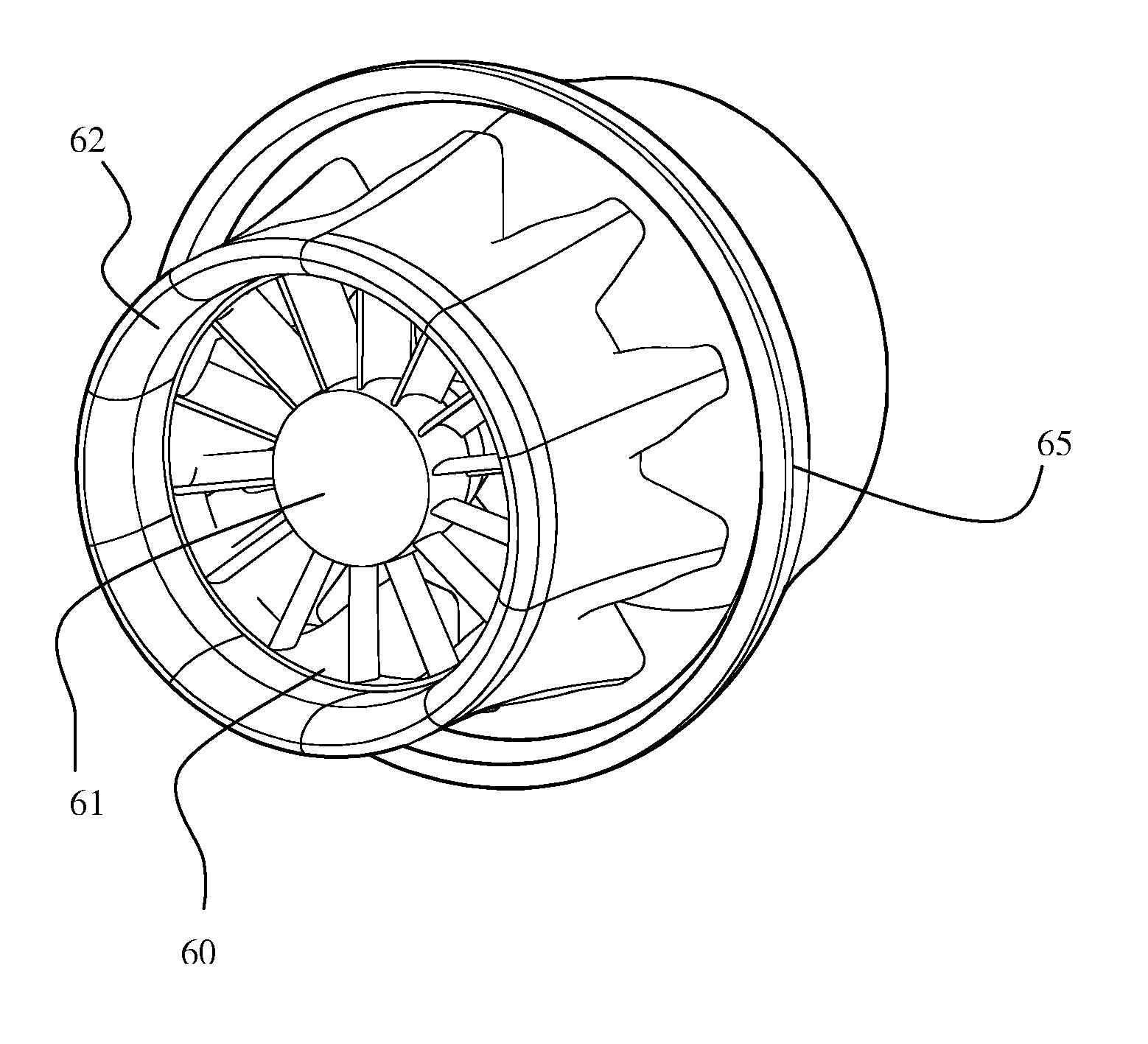
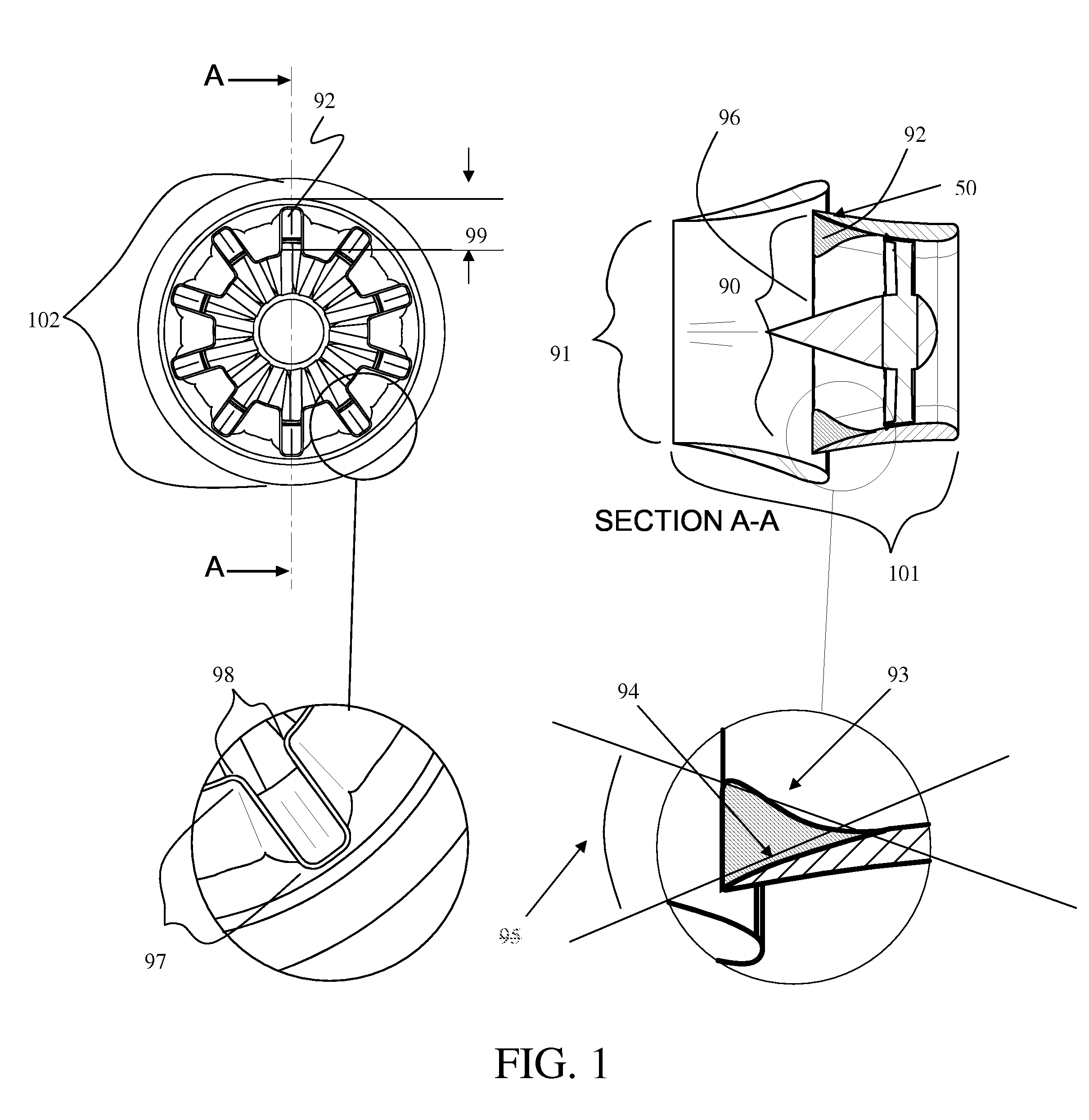
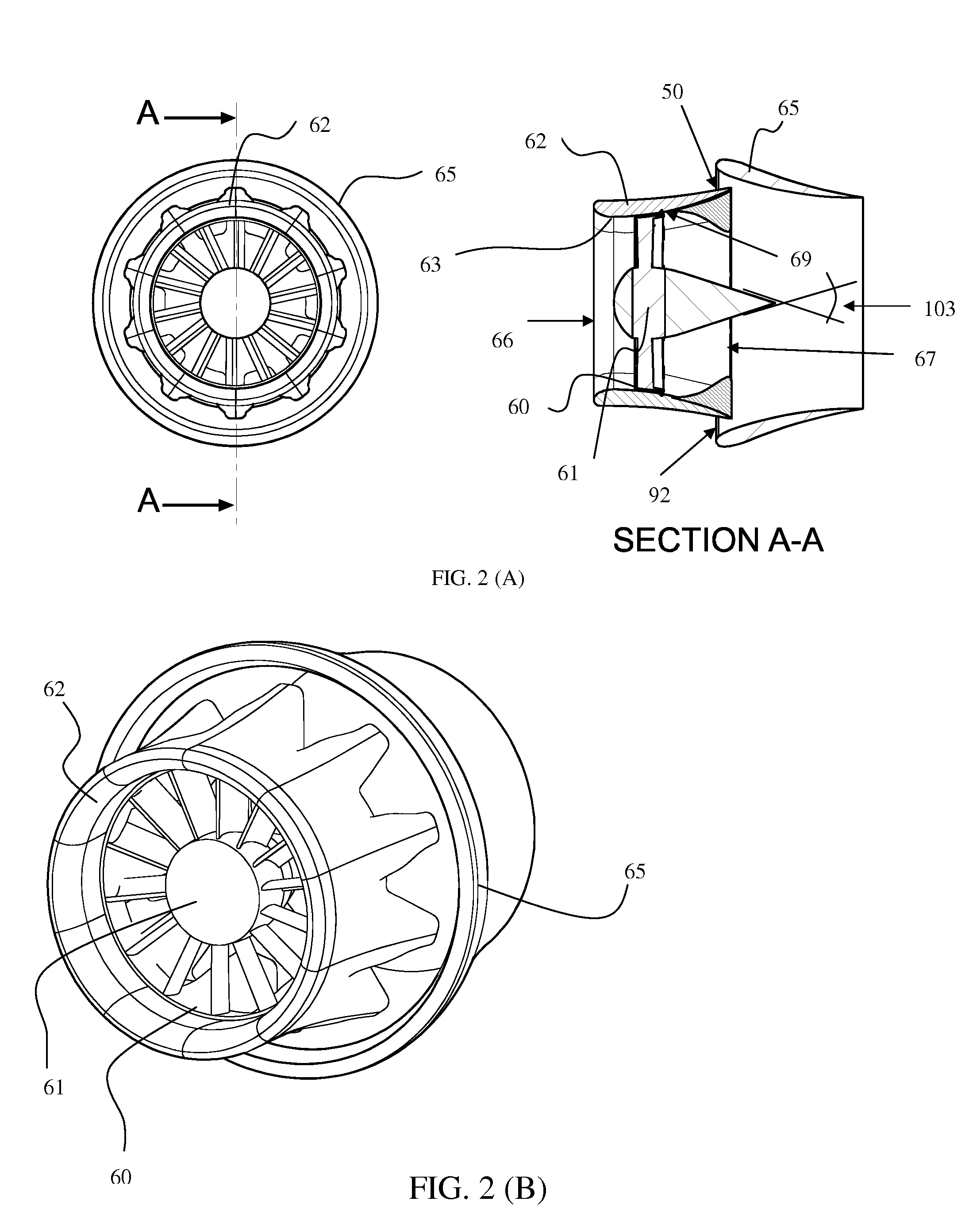
[0025]Referring to the drawings in detail, Applicants' novel mixer-ejector propeller system (nicknamed the “MEPS”) is disclosed and like reference numerals refer to like elements. MEPS combines advanced flow mixing devices (hereinafter “MIXERS”), ejector pumps (hereinafter “EJECTORS”) and propellers (hereinafter “PROPs”) elements for increasing force generated in a fluid stream.

[0026]The MEPS uses aerodynamically contoured shrouds and ejectors surrounding a propeller system which consists of one or more rows of blades to input power to the oncoming fluid stream. The shrouds and ejectors are designed and arranged so as to draw the maximum amount of fluid through the propeller for maximum propulsion efficiency. First-principles-based theoretical analysis of MEPS indicate that they can increase propulsion by fifty percent or more when compared to the thrust produced by un-shrouded counterpart propellers for the same frontal area and power input.

[0027]In the first preferred embodiment, ...


PUM


Abstract

A Mixer-Ejector Prop System (MEPS) is presented as a new, unique and improved concept for injecting power and producing force in flowing fluids such as air or water. MEPS incorporates advanced flow mixing technology, single and multi-stage ejector technology, aircraft and propulsion aerodynamics and noise abatement technologies in a unique manner to fluid-dynamically improve the operational effectiveness and efficiency for subsonic flow velocities.

Description

RELATED APPLICATION[0001]This application claims priority from U.S. Provisional Patent Applications Ser. No. 60 / 919,588, filed Mar. 23, 2007. Applicants hereby incorporate the disclosure of that application by reference.BACKGROUND OF INVENTION[0002]A propeller rotor device, termed the “prop”, is a series of aerodynamic blades that are rotated by a power source such that energy is added to the flow passing through the prop. In most applications such added energy is used to generate an axial, propulsive force at speeds less than 300 miles per hour, hereinafter “low speed flow”. The number, shape and design of the rotating prop blades can vary. Two example applications of such props are in the propulsion systems of aircraft and watercraft. Variations of such props are used in axial flow rotors of a compressor. They are also used to drive blower and vacuum systems.[0003]The ability of a prop to convert power to force when placed in a stream of very large width compared to its diameter i...

Claims


Application Information

Patent Timeline
Patent Type & Authority Applications(United States)
IPC IPC(8): F04D29/52F04D29/32
CPCF03D1/04F05B2210/16Y02E10/721F05B2240/133F05B2260/96F05B2240/13Y02E10/728Y02E10/72F03D9/32
Inventor WERLE, MICHAEL J.PRESZ, JR., WALTER M.
Owner FLODESIGN WIND TURBINE
Why Eureka
Try Eureka