
Battery layout incorporating full metal edge seal

a technology of edge sealing and battery, applied in the direction of flat cell grouping, cell components, sustainable manufacturing/processing, etc., can solve the problems of not being able to meet the requirements of a single device, needing to include the power supply with the device, and fabricated from potentially toxic materials. , to achieve the effect of exceptional coverage and protection

Active Publication Date: 2009-08-27
CYMBET CORP
View PDF20 Cites 55 Cited by
  • Summary
  • Abstract
  • Description
  • Claims
  • Application Information

AI Technical Summary

Benefits of technology

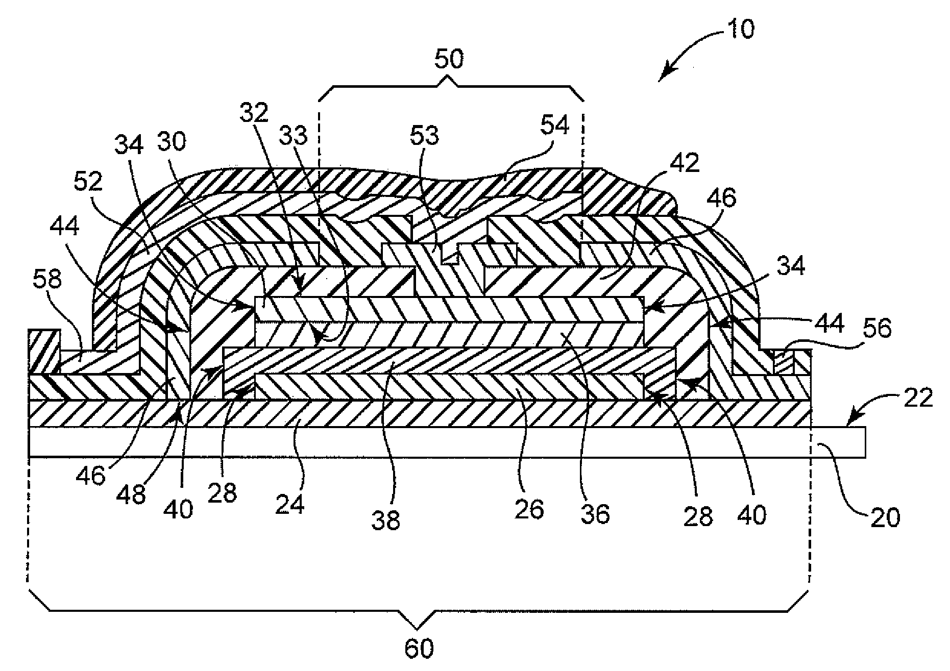
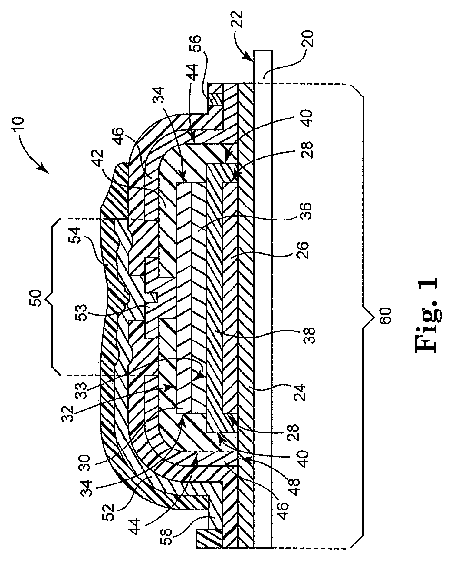
[0010]This unique construction of the thin film battery provides exceptional coverage and protection of, in particular, the sides of the battery, by providing a complete metal to metal boundary seal around the entire battery perimeter. This layout prevents adverse environmental exposure of edges of adjacent metal and non-metal layers that would provide a direct lateral pathway to sensitive components of the battery construction along a metal / non-metal interface.

Problems solved by technology

One drawback to portable devices is the need to include the power supply with the device.
Sufficient battery capacity can result in a power supply that is quite heavy and / or large compared to the rest of the device.
Another drawback of conventional batteries is the fact that some are fabricated from potentially toxic materials that may leak and be subject to governmental regulation.

Method used


Image

  • Battery layout incorporating full metal edge seal
  • Battery layout incorporating full metal edge seal

Examples


Embodiment Construction

[0013]The embodiments of the present invention described below are not intended to be exhaustive or to limit the invention to the precise forms disclosed in the following detailed description. Rather a purpose of the embodiments chosen and described is so that the appreciation and understanding by others skilled in the art of the principles and practices of the present invention can be facilitated.

[0014]Terminology

[0015]In this description, the term metal applies both to substantially pure single metallic elements and to alloys or combinations of two or more elements, at least one of which is a metallic element.

[0016]The term substrate or core generally refers to the physical structure that is the basic work piece that is transformed by various process operations into the desired microelectronic configuration. In some embodiments, substrates include conducting material (such as copper, stainless steel, aluminum and the like), insulating material (such as sapphire, ceramic, or plasti...


PUM


Abstract

A first current collector on the first surface of the substrate and a second current collector having a first surface and a perimeter. One of the first and second current collector is an anode current collector and the other is a cathode current collector. The battery also comprises a cathode material having a perimeter, the cathode material being located on the cathode current collector; an electrolyte layer having a perimeter, the electrolyte separating the cathode material from the anode current collector; an insulation layer having a perimeter, the insulation layer together with the electrolyte layer separating the anode current collector from the cathode material and the cathode current collector. A first passivation layer generally overlies at least the perimeter of the cathode material, the perimeter of the electrolyte, and the perimeter of the insulation layer, the first passivation layer being electrically coupled to the first current collector and forming a continuous metal to metal seal around a defined area of the first current collector. The first passivation layer has a via opening. A second passivation layer is electrically coupled to the second current collector through the via opening of the first passivation layer.

Description

[0001]This application claims the benefit of U.S. Provisional Application Ser. No. 61 / 067,288 filed on Feb. 27, 2008, entitled “BATTERY LAYOUT INCORPORATING FULL METAL EDGE SEAL,” which application is incorporated herein by reference in its entirety.FIELD OF THE INVENTION[0002]This invention relates to the field of thin-film solid-state energy-storage devices, and more specifically to construction and design of thin-film solid-state batteries.BACKGROUND OF THE INVENTION[0003]Electronics have been incorporated into many portable devices such as computers, mobile phones, tracking systems, scanners, etc. One drawback to portable devices is the need to include the power supply with the device. Portable devices typically use batteries as power supplies. Batteries must have sufficient capacity to power the device for at least the length of time the device is in use. Sufficient battery capacity can result in a power supply that is quite heavy and / or large compared to the rest of the device...

Claims


Application Information

Patent Timeline
IPC IPC(8): H01M6/02H01M10/36H01M50/109H01M50/543H01M50/548
CPCH01M2/0222H01M2/0426H01M2/08H01M10/0585H01M2/30H01M10/0436H01M10/0525H01M2/26Y02E60/10H01M50/109H01M50/169H01M50/543Y02P70/50H01M50/548H01M10/0562H01M10/052H01M2300/0068H01M50/183H01M50/531
Inventor SHAKESPEARE, STUART KEVINSTANISLOWSKI, STANLEY JACOBHOLMQUIST, DEBRA ANNKROELLS, DARRENFLATLAND, MATTHEWFLEMMER, THEODORE L.MCKINLEY, STEVEN J.
Owner CYMBET CORP
Learn More