Modular slim connector

a technology of modular connectors and connectors, applied in the direction of couplings/cases, coupling device connections, incorrect coupling prevention, etc., can solve the problems of greater difficulty in preparing molds and relatively difficult preparation of formed bodies, so as to facilitate production, increase the area of force application, and facilitate the effect of molding

Active Publication Date: 2009-08-27
MOLEX INC
View PDF7 Cites 19 Cited by
  • Summary
  • Abstract
  • Description
  • Claims
  • Application Information

AI Technical Summary

Benefits of technology

[0013]With the design of the two lateral protruding edges which protrude from the side surfaces at locations adjacent to the first mating surface, and preferably by having one side of each of the lateral protruding edges forms a continuous flat surface with the first mating surface, the shapes of the first insulating housing and the matching second insulating housing are neat, rendering mold making easier, and also facilitating production. Further, the first insulating housing can be formed with a lower protruding edge and an upper protruding edge connected to the two lateral protruding edges to increase the area for application of force to grip the first electrical connector, so as to facilitate assembly of the first electrical connector with an electronic device.
[0014]Therefore, an object of the present utility model is to provide a floating type electrical connecting device whose insulating housing structure is more convenient to manufacture.
[0015]Another object of the present utility model is to provide a floating type electrical connecting device with better strength.

Problems solved by technology

Enabling horizontal plugging connection or vertical plugging connection of the first electrical connector 91 to the second electrical connector 92 multiple times is to overcome the drawback of prior floating type electrical connector assemblies, such as that disclosed in R.O.C. Utility Model Patent No. 265798, which are not suitable for multiple plugging connections because the adapting segments of the conductive terminals of the electrical connectors therein are suspended and easily damaged if subjected to multiple plugging connections.
Since current methods for manufacturing insulating housings mainly involve use of injection molding processes for relative ease and convenience, if the shapes of the insulating housings are more irregular, the difficulty in preparing the molds is greater, and it is relatively not easy to prepare the formed bodies.

Method used


Image

  • Modular slim connector
  • Modular slim connector
  • Modular slim connector

Examples


Embodiment Construction

[0037]Before the present utility model is described in detail, it should be noted that in the following description content, similar components are represented by identical numerals.

[0038]In order to make the insulating housings easier to manufacture, the inventor of the present application continued with the concept of the prior art that the first electrical connector and the second electrical connector can be plugged and unplugged multiple times, and further modified the shapes of the insulating housing of the first electrical connector and the insulating housing of the second electrical connector.

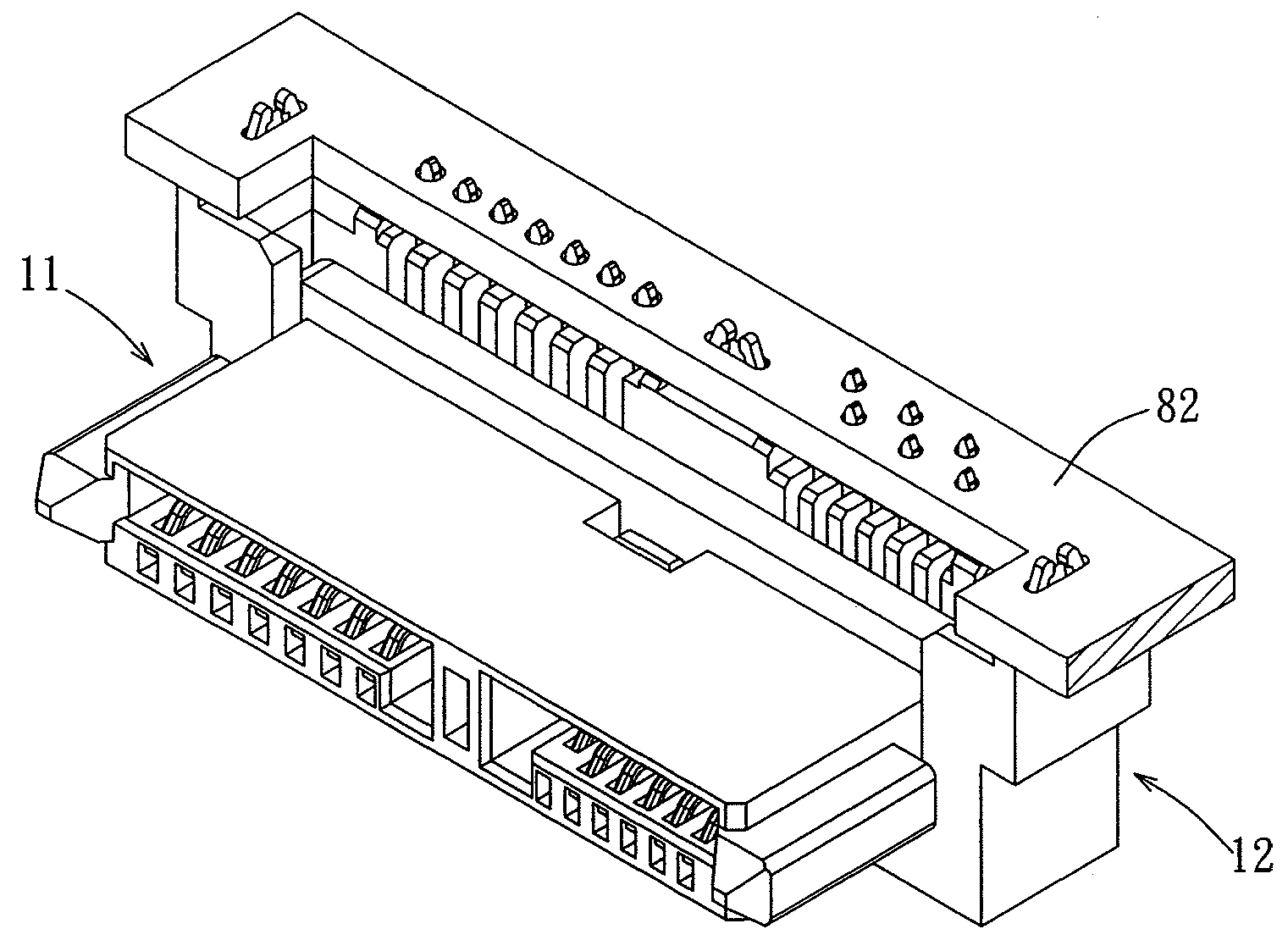
[0039]The insulating housing of the first electrical connector is formed with a vertical lateral protruding edge at each of left and right sides of a mating surface thereof, such that the vertical lateral protruding edges on the two sides serve as guiding rails, and can be engaged slidingly with matching sliding grooves in two sides of the insulating housing of the second electrical conn...


PUM


Abstract

A floating type electrical connecting device, comprises: first and second electrical connectors. The first electrical connector includes a first insulating housing, and a plurality of first conductive terminals. The first insulating housing has a first mating surface, a plugging surface located on an opposite side of the first mating surface, two side surfaces respectively connected at opposite left and right sides of the first mating surface and the plugging surface, and a plurality of first terminal grooves extending from the mating surface to the plugging surface through the first insulating housing. In addition, a vertical lateral protruding edge is formed at each side surface adjacent to the first mating surface, and protruding from the side surface. The second electrical connector includes a second insulating housing, and a plurality of second conductive terminals. The second insulating housing has two sliding grooves respectively for receiving the two lateral protruding edges.

Description

RELATED CASES[0001]This application claims priority to Taiwan Application 96221517, filed Dec. 18, 2007, which is incorporated herein by reference in its entirety.FIELD OF THE INVENTION[0002]The present utility model relates to an electrical connector, more particularly to a floating type electrical connector that permits easy mold making, that is convenient to manufacture, and that has better strength.BACKGROUND OF THE INVENTION[0003]With reference to FIG. 1, FIG. 2 and FIG. 3, R.O.C. Utility Model Patent No. 306729 owned by the applicant discloses a floating type electrical connector assembly 90, which comprises a first electrical connector 91 for assembly and electrical connection to an electronic device 901, and a second electrical connector 92 for mounting on an electrical circuit board 902.[0004]Each conductive terminal 93 of the first electrical connector 91 is formed with a flat plate-shaped adapting segment 931, and the adapting segments 931 can be supported by a first insu...

Claims


Application Information

Patent Timeline
Patent Type & Authority Applications(United States)
IPC IPC(8): H01R13/64
CPCH01R13/46H01R12/716H01R12/7029H01R13/6315
Inventor TSENG, TING-CHANG
Owner MOLEX INC
Why Eureka
Try Eureka