Game racket including a pivot element

a pivot element and game racket technology, applied in the field of game rackets, can solve the problems of typical heavyness, achieve the effect of reducing the need for protective string grommets, enhancing the performance of game rackets, and avoiding frictional mechanical interactions

Inactive Publication Date: 2009-08-27
BOTHWELL BRETT
View PDF7 Cites 16 Cited by
  • Summary
  • Abstract
  • Description
  • Claims
  • Application Information

AI Technical Summary

Benefits of technology

[0005]To further enhance the performance of a game racket it is another object of the present invention to utilize a spring-like pivot mechanism to flexibly resist torsion brought on by ball impact. Another objective is to have a protective bumper that could serve as both a guard and a spring.
[0006]It would be another improvement to have a mechanism on the head frame of a game racket such that the string rebound force could be controlled in an efficient manner. It's another object of the present invention to provide a mechanism on the head frame of a game racket that can be controlled either manually or automatically in order to control the response of the strings. It's still another objective to have a pivoting mechanism on the head frame of a racket capable of being controlled by an electronic signal. It is a further objective to have a pivoting mechanism magnetically levitated in relation to the head frame of a racket in order to achieve a “frictionless” mechanical interaction.
[0007]It is another objective to provide the pivot element of the present invention with pre-formed string hole openings and therefore to eliminate the need for protective string grommets. It is yet another object to maximize leverage of a string on a pivot mechanism.

Problems solved by technology

The reality of most mechanisms on rackets has been that they were typically too heavy.

Method used


Image

  • Game racket including a pivot element
  • Game racket including a pivot element
  • Game racket including a pivot element

Examples


first embodiment

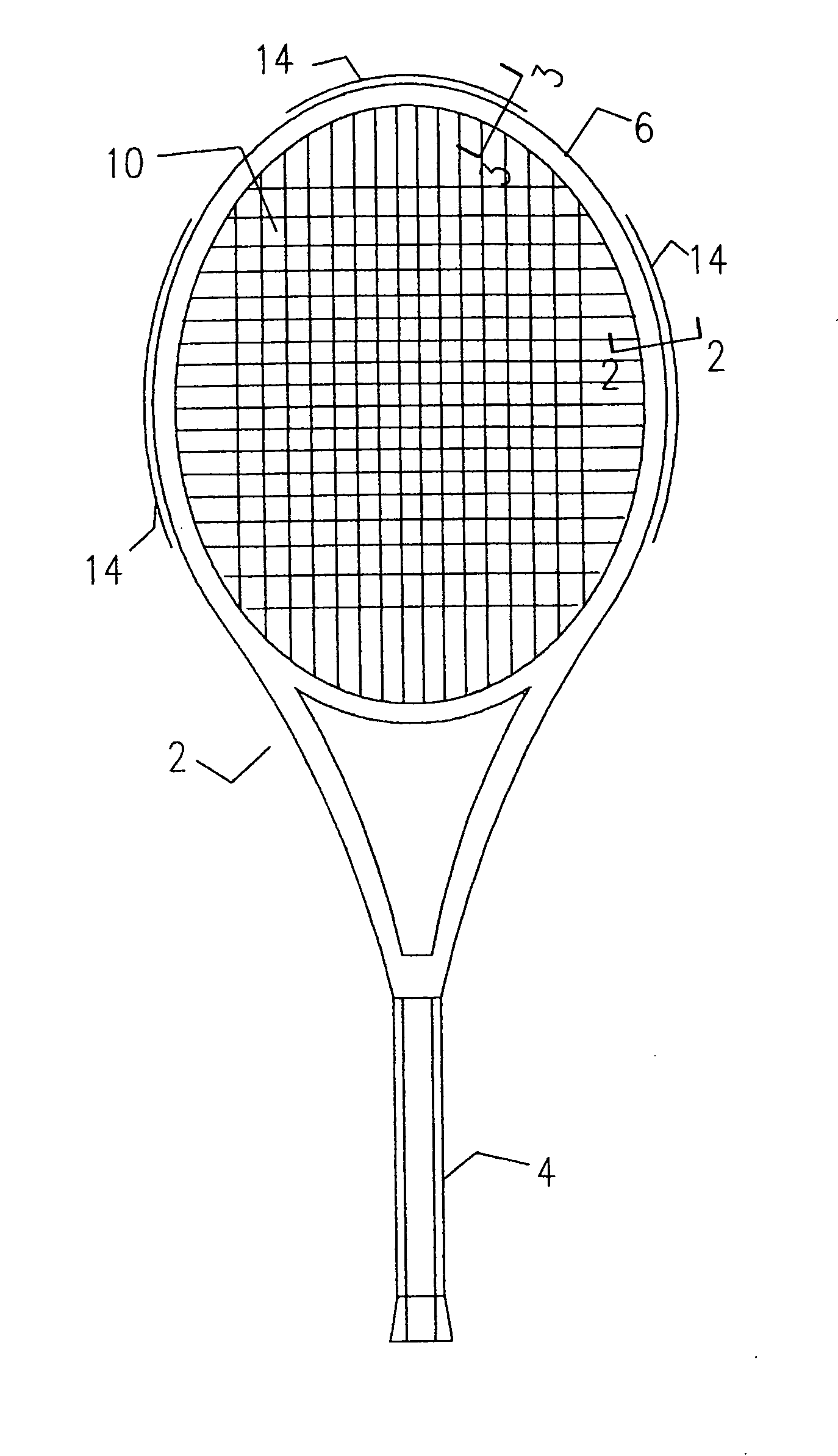
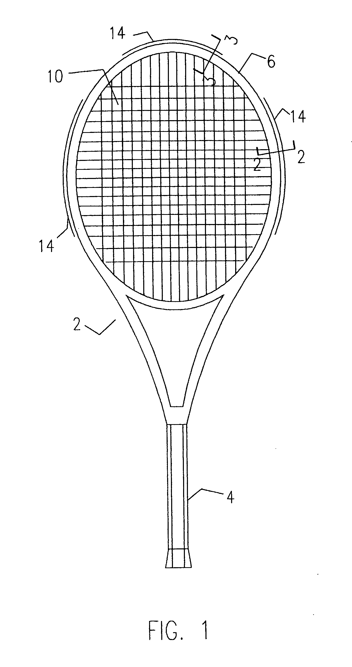
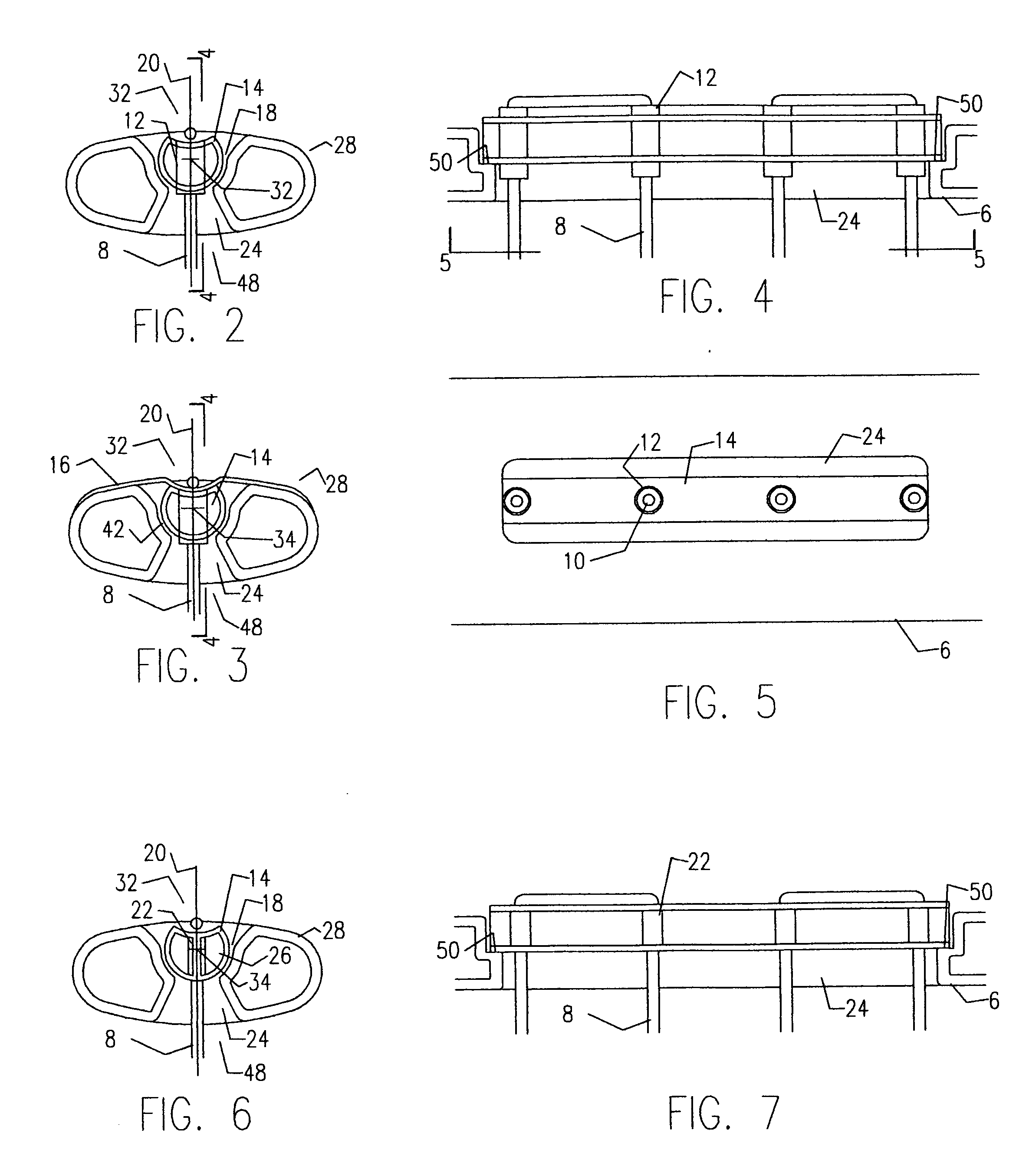
[0036]FIG. 2 shows a cross-sectional view corresponding to line 2-2 in FIG. 1 of a pivot element 14 located partially within a substantially circular mating recess 18 on an outer-facing peripheral surface 32 of a head frame profile 28. The pivot element 14 is hollow and generally tubular and has a substantially circular profile. The element 14 has at least one string 8 laced through its central rotational axis 34 and is aligned with a central axis of the mating recess 18. In this particular embodiment a string 8 is shown laced through a string channel opening 24 in a head frame profile 28 and through a protective grommet 12 that is inserted in a string hole opening 30 in the pivot element 14. When ball impact on the string 8 occurs, a moment force is created around the central rotational axis 34 of the pivot element 14, forcing it to rotate within the mating circular recess 18 of the head frame profile 28.

[0037]An important way to affect the rotational efficiency of the pivot elemen...

third embodiment

[0051]FIG. 15 shows a cross-sectional view corresponding to line 2-2 in FIG. 1 of a spring-loaded pivot element 14. This particular element 14 has 2 wing(s) 36 extending away from its central axis 20 in two directions perpendicular to a string 8, which rest on an outside-facing peripheral surface 32 of a head frame profile 28. The 2 wing(s) of this arrangement form a chamber 40 that can be utilized to affect the flexural capacity of the wing 36 and therefore the capacity of the pivot element 14 to resist a moment force brought on by ball impact. In this particular embodiment a string 8 is shown laced through a grommet 12 that's inserted through the pivot element 14 however, the design could just as easily be made from more than one component 26 to have pre-formed string hole openings 22 thereby eliminating the need for a protective string grommet 12.

[0052]FIG. 16 shows a cross-sectional view corresponding to line 2-2 in FIG. 1 of a two-component 26 pivot element 14 located partially...


PUM


Abstract

The present invention is intended for use as a game racket including a handle and a head frame with strings held in tension. In particular as a high performance game racket frame including at least one generally tubular, substantially circular pivot element located at least partially within a substantially circular mating recess on at least one portion of an outside-facing peripheral surface of the head frame profile that can rotate to cooperate with at least one string. The pivot element can rest upon at least a portion of the mating recess and therefore can have at least one adjoining surface portion. In order to reduce friction, adjoining surface(s) can be coated with a suitable anti-friction agent such as silicone or it can include a “frictionless” repelling permanent magnet portion capable of sustaining magnetic levitation between the two parts. Alternatively, at least a portion of the adjoining surfaces can include communicating electromagnetic friction plates in order to control the rate at which the pivot element rotates.

Description

FIELD OF THE INVENTION[0001]The present invention is intended for use as a game racket including a handle and a head frame with strings held in tension. In particular as a high performance game racket frame including at least one pivot element located on at least one portion of the head frame to cooperate with at least one string.BACKGROUND INFORMATION[0002]Enhancing the response of the stringbed of a game racket is a common theme in the history of racket design. Many designs have included mechanisms such as springs, rollers, levers, etc. in order to improve the response of the strings. The reality of most mechanisms on rackets has been that they were typically too heavy. Modem inflation bladder molding techniques and reinforced plastic construction make it possible now however, to employ similar mechanisms in lighter and more efficient ways.[0003]It's possible now to replicate some of the functions of simple mechanisms like levers, wheels, and springs with lightweight reinforced pl...

Claims


Application Information

Patent Timeline
Patent Type & Authority Applications(United States)
IPC IPC(8): A63B51/12
CPCA63B49/002A63B49/007A63B49/14A63B2209/08A63B51/12A63B59/0074A63B2209/00A63B51/00A63B49/022A63B49/028A63B60/42A63B60/00
Inventor BOTHWELL, BRETT
Owner BOTHWELL BRETT
Why Eureka
Try Eureka