Device and Method for an Automatic Treadmill Therapy

a technology of automatic treadmill and treadmill speed, which is applied in the direction of walking aids, physical therapy, chiropractic devices, etc., can solve the problems of not being usable and difficult to use this device for therapeutic purposes with variable treadmill speed

Inactive Publication Date: 2009-08-27
ETH ZZURICH
View PDF13 Cites 30 Cited by
  • Summary
  • Abstract
  • Description
  • Claims
  • Application Information

AI Technical Summary

Benefits of technology

[0006]An object of the present invention is to provide a method and a device, which gives a person the possibility for automatic treadmill training with variable treadmill speed.
[0008]This will provide realistic conditions for a person who relearns walking with such a method.

Problems solved by technology

For patients this is not usable because the patient has to concentrate on the motion sequence.
Due to this inaccuracy it is difficult to use this device for therapeutical purposes with variable treadmill speed.

Method used


Image

  • Device and Method for an Automatic Treadmill Therapy
  • Device and Method for an Automatic Treadmill Therapy
  • Device and Method for an Automatic Treadmill Therapy

Examples


second embodiment

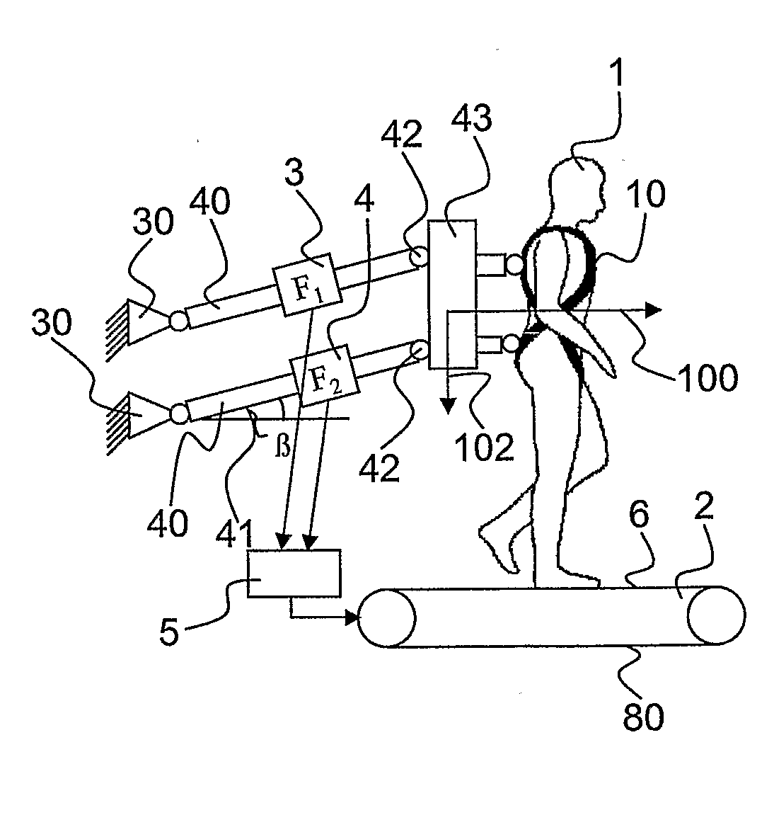
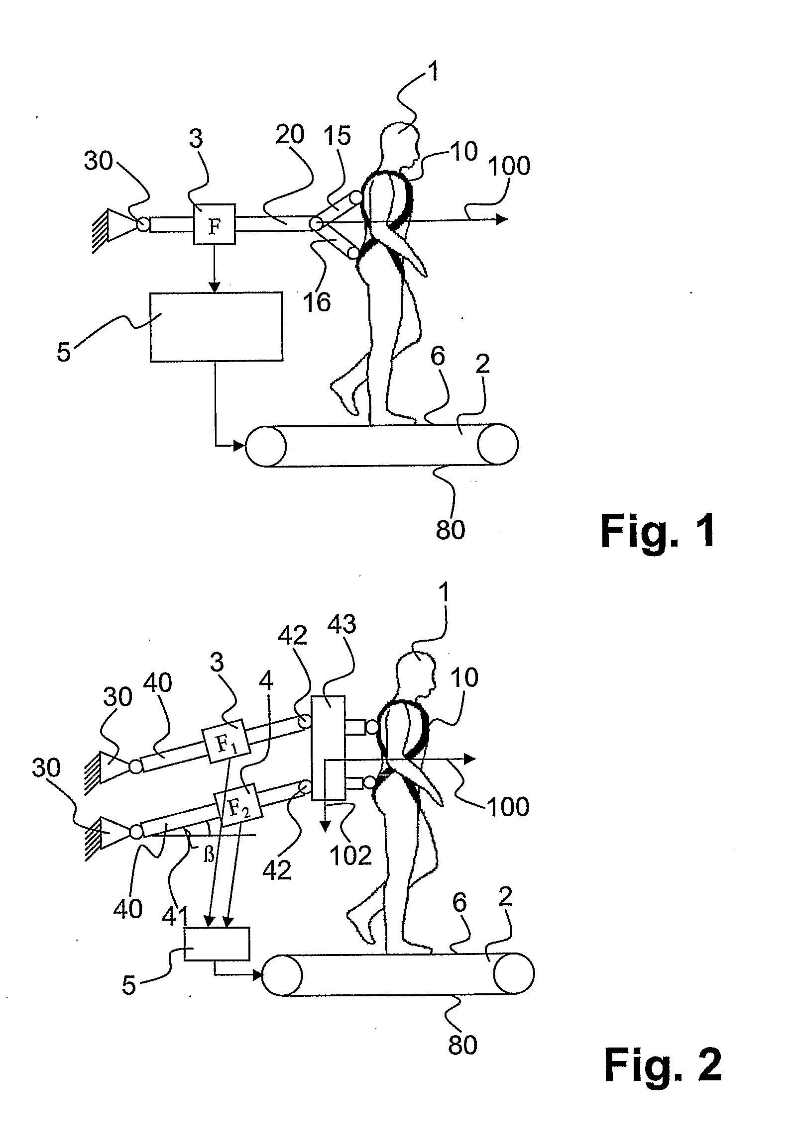
[0033]FIG. 2 shows a second embodiment according to the present invention. The patient is fixed to a plate 43 by the fixation means 10 as already described. On one end, the two rods 40 are connected to the plate 43 with bearings 42. The plate 43 may provide the possibility to fix the orthosis. On the other end the two rods 40 are connected to the bearings 30. The distance from one bearing 30 to another bearing 30 is the same as the distance from one bearing 42 to the other bearing 42. Since the two rods 40 have the same length, a parallelogram. is formed. The parallelogram lies with an angle β to the horizontal base plane 6. The angle β depends on the height of the patient 1 and it varies with the up and down movement of the patient 1. The bearings 30 are hinge bearings that allow only pivoting movements in the sagittal plane.

[0034]The axial forces in rods 40 are measured by measure means 3, 4. This arrangement of rods, bearings, and force sensors allows an easy determination of the...

third embodiment

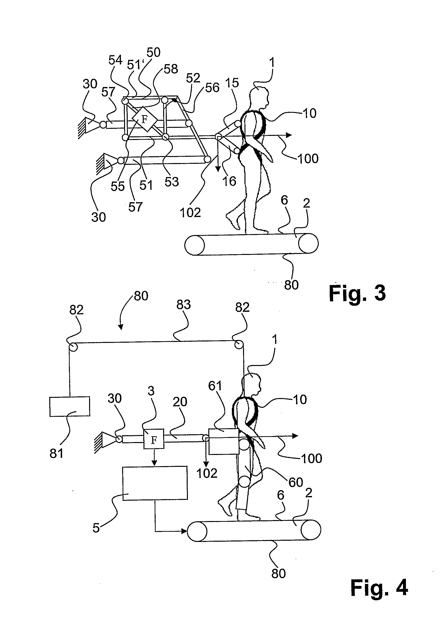
[0038]FIG. 3 shows a further third embodiment according to the present invention. The patient 1 is connected to the mechanical rod system as described in FIG. 1. The rod 20 as introduced in FIG. 1 is now replaced by rod 51 which is one of the horizontal rods of a linkage 50. The linkage 50 comprises two horizontal rods 51 and two vertical rods 52 that are arranged in a rectangle. The horizontal rod 51 is longer than the other horizontal rod 51′ and both are arranged in a way that one end protrudes the vertical rod 52. A diagonal rod 58 connects a first corner 53 of the parallelogram to a second corner 54 of the parallelogram. The diagonal rod 52 is equipped with a force sensor 55. The horizontal rod 51′ and the linker rod 56 are rigidly connected to each other, for example welded. Via the horizontal rod 51′ and a linker rod 56 the linkage 50 is connected to main rods 57. The two main rods 57 are supported by the bearings 30.

[0039]Due to the arrangement of the linkage, the vertical f...

fourth embodiment

[0041]FIG. 4 shows a fourth embodiment similar to the embodiment of FIG. 1. Additionally to FIG. 1 a driven orthotic device 60 provides aid to the patient in order to learn a proper motion sequence. The orthotic device 60 may be according to the device as described in WO 0028927, which may also be designated as gait-robot or lokomat. The orthotic device 60 is connected via a plate 61 to the rod system as already described.

[0042]During the training a repulsion force between the treadmill 2 and the person 1 occurs. Force measure means 3 measure a reaction force that occurs due to the longitudinal repulsion force.

[0043]Additionally to the orthotic device 60 the patient may be supported by a relieve mechanism 80. A suspended weight 81 is arranged on one end of a cable 83. The cable 83 is diverted over two pulleys 82. On the other end the cable 83 is attached to the harness 10 of the patient 1. Due to the weight 81 on one end the patient 1 will be relieved from a part of his own weight. ...


PUM


Abstract

A method to control the velocity of a treadmill according to the walking velocity of the person that is using the treadmill. A reaction force is measured, which occurs when a longitudinal repulsion force is created between the treadmill (2) and the person (1). A signal representation for said reaction force is transmitted to a control unit. The control unit is used to control the velocity of the treadmill.

Description

FIELD OF THE INVENTION[0001]The invention relates to a device for adjusting the speed of a treadmill, which is used for the therapy of paraplegic or hemiplegic patients and other neurological as well as orthopaedical patient groups as well as for the (fitness) training of healthy or elderly subjects.PRIOR ART[0002]Treadmills are known by prior art for example from EP 0 002 188. The speed of the treadmill varies according to the heart frequency of the patient. If the heart frequency reaches an upper limit, the speed of the treadmill decreases. The heart frequency is a parameter that is not applicable in the therapy of paraplegic patients, since the purpose of the therapy is the ability of a proper motion sequence and the heart frequency does not change in a manner that is usable for this purpose.[0003]U.S. Pat. No. 5,707,319 discloses a treadmill with two lever to pull in order to adjust the belt speed. For patients this is not usable because the patient has to concentrate on the mot...

Claims


Application Information

Patent Timeline
Patent Type & Authority Applications(United States)
IPC IPC(8): A63B24/00
CPCA61H1/0237A61H3/008A61H2001/0211A63B22/0023A63B22/02A63B22/0235A61H2201/5061A63B2220/51A61H3/00A61H2201/1616A61H2201/1621A61H2201/163A61H2201/1652A63B2022/025A63B22/025
Inventor RIENER, ROBERTBERNHARDT, MICHAELVON ZITZEWITZ, JOACHIM
Owner ETH ZZURICH
Why Eureka
Try Eureka