Power assist apparatus and control method thereof

a technology of assist apparatus and control method, which is applied in the direction of computer control, program control, special data processing applications, etc., can solve the problems of workpiece or attachment subject member to break, workpiece may tilt, and workpiece or attachment subject to break, so as to improve positioning accuracy, improve efficiency, and fine positioning

Active Publication Date: 2009-08-27
TOYOTA JIDOSHA KK
View PDF17 Cites 19 Cited by
  • Summary
  • Abstract
  • Description
  • Claims
  • Application Information

AI Technical Summary

Benefits of technology

[0009]To improve the efficiency with which a workpiece is conveyed by a power assist apparatus and improve positioning accuracy when the workpiece is attached using the power assist apparatus, the inv

Problems solved by technology

However, depending on the state of balance (center of gravity position) of the workpiece, the workpiece may tilt unexpectedly about the respective joint portions as soon as the locks on the respective joint portions are released when the operator grips the workpiece holding apparatus.
In this case, the operator may be unable to support this displacement, and as a result, the workpiece may contact an attachment subject member, causing either the workpiece or the attachment subject member to break.
Furthermore, allowing

Method used


Image

  • Power assist apparatus and control method thereof
  • Power assist apparatus and control method thereof
  • Power assist apparatus and control method thereof

Examples


Embodiment Construction

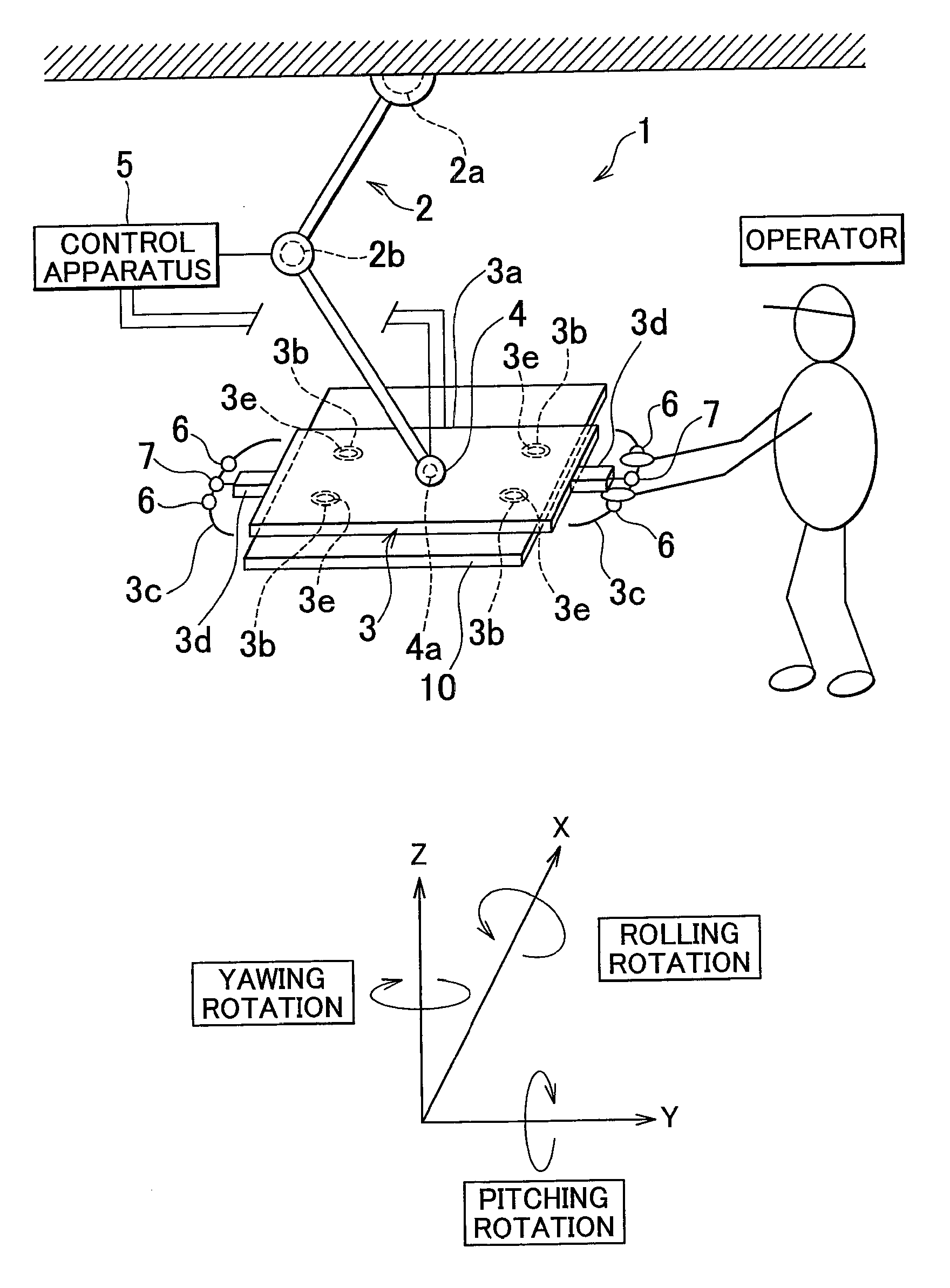
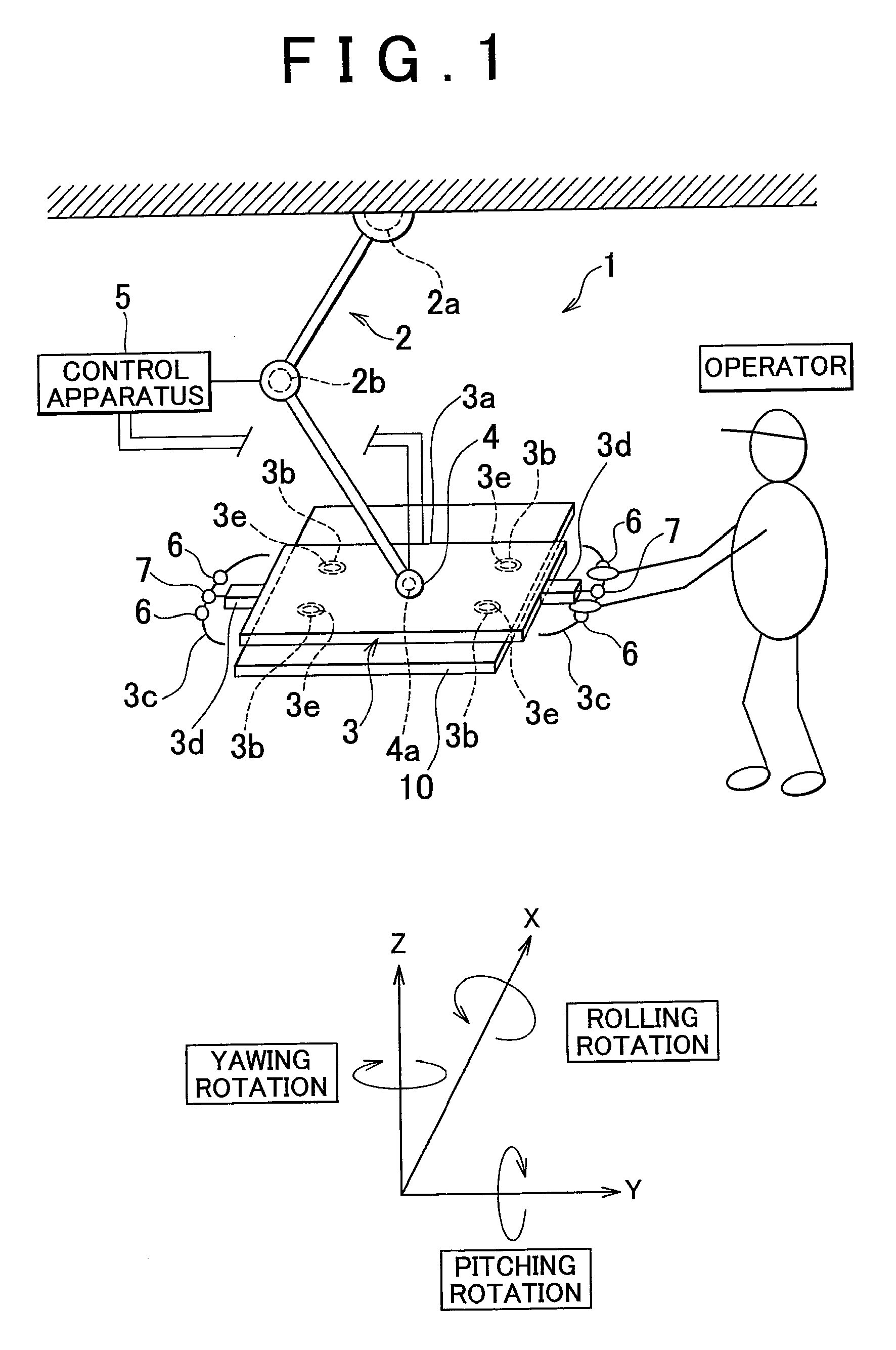
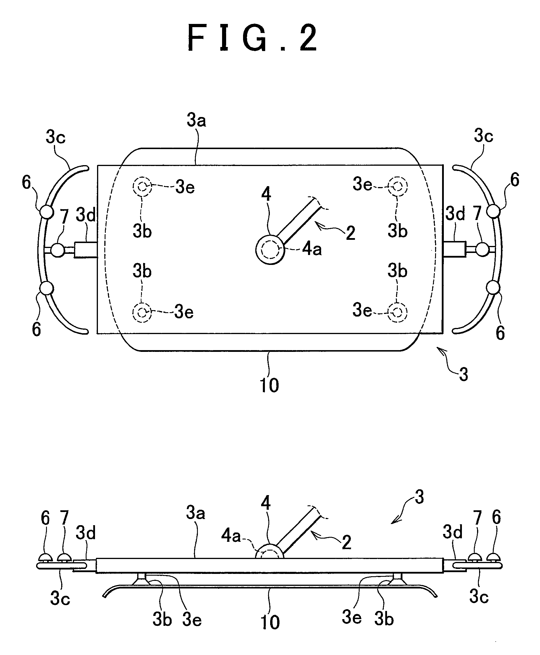
[0035]First, the overall constitution of a power assist apparatus 1 according to an embodiment of the invention will be described using FIGS. 1 to 3. FIG. 1 is a schematic diagram showing the overall constitution of the power assist apparatus according to an embodiment of the invention. FIG. 2 is a schematic plan view and a schematic side view showing a workpiece holding apparatus according to an embodiment of the invention. FIG. 3 is a schematic diagram showing a connection condition of a control apparatus according to an embodiment of the invention. Note that for ease of description, it is assumed that the power assist apparatus is provided on an XYZ coordinate system shown in FIG. 1, wherein rotation about the X axis denotes rolling rotation, rotation about the Y axis denotes pitching rotation, and rotation about the Z axis denotes yawing rotation. As shown in FIG. 1, the power assist apparatus 1 according to this embodiment is constituted by an articulated robot 2, a workpiece h...


PUM


Abstract

In a control method for a power assist apparatus, a pressing force acting on a workpiece held by a workpiece holding apparatus is detected, a determination is made as to whether or not the detected pressing force exceeds a preset threshold, a determination is made as to whether or not a dead man switch provided on the workpiece holding apparatus is ON, and a determination as to whether or not to release a rotation restriction applied to a joint portion for connecting the workpiece holding apparatus rotatably to an arm is made in accordance with a result of the determination as to whether or not the detected pressing force exceeds the preset threshold and a result of the determination as to whether or not the dead mean switch is ON.

Description

INCORPORATION BY REFERENCE[0001]The disclosure of Japanese Patent Application No. 2008-45010 filed on Feb. 26, 2008, including the specification, drawings and abstract is incorporated herein by reference in its entirety.BACKGROUND OF THE INVENTION[0002]1. Field of the Invention[0003]The invention relates to a power assist apparatus and a control method for a power assist apparatus.[0004]2. Description of the Related Art[0005]In manufacturing sites and the like for manufacturing industrial products, a power assist apparatus is used as an apparatus for assisting an operator in the conveyance of heavy loads (workpieces). A workpiece attachment operation includes conveyance and positioning of the workpiece, but when the workpiece is conveyed cooperatively by the operator and the power assist apparatus, the power required to convey the workpiece can be provided by the power assist apparatus. Moreover, by teaching the power assist apparatus, positioning of the workpiece can be performed e...

Claims


Application Information

Patent Timeline
IPC IPC(8): G05B19/06
CPCB25J9/107B25J13/085B25J15/0616G05B2219/39447B66C23/005G05B2219/36429B66C1/0243
Inventor MURAYAMA, HIDEYUKI
Owner TOYOTA JIDOSHA KK
Why Eureka
Try Eureka