Supercharge Your Innovation With Domain-Expert AI Agents!

Hierarchy of diagnosis for advanced diagnostics equipment

Inactive Publication Date: 2009-08-27
SPX CORP
View PDF26 Cites 16 Cited by
  • Summary
  • Abstract
  • Description
  • Claims
  • Application Information

AI Technical Summary

Benefits of technology

[0016]The diagnostic tool can also have the processor accepting a selection of the hierarchy according to the inputted selection. The diagnostic tool can also include the housing encasing the signal translator, the input device, an input and output unit, the processor, the memory, and the display unit for storing and processing the hierarchical information of a diagnostic procedure. The diagnostic tool can also include a connector interface that connects the signal translator with a vehicle interface through one of a wired and wireless link to allow for recording of the diagnostic data between the diagnostic tool and the vehicle.

Problems solved by technology

Onboard control computers have become prevalent in motor vehicles, but as safety, economy, and emissions requirements have continued to tighten, friction braking systems, and traction control devices have not met the requirements set out in government regulations and the implicit demands of competitors' achievements.
Present external diagnostic and display apparatus, known as diagnostic tools, are commonly limited to reporting the data acquired by the onboard control computer itself.
Increasingly, subtle subsystem failures in vehicles overload the ability of maintenance technicians, not simply to read the faults detected and stored by the diagnostic tools themselves, but to combine those readings with peripheral measurements and deduce corrective actions with both speed and accuracy.
With such a system, a relatively inexperienced operator may perform advanced diagnostic procedures and diagnose complex operational or medical problems.
Such limitations have caused the necessity of creating the same type of diagnostic charts for different vehicle groups.

Method used


Image

  • Hierarchy of diagnosis for advanced diagnostics equipment
  • Hierarchy of diagnosis for advanced diagnostics equipment
  • Hierarchy of diagnosis for advanced diagnostics equipment

Examples


Embodiment Construction

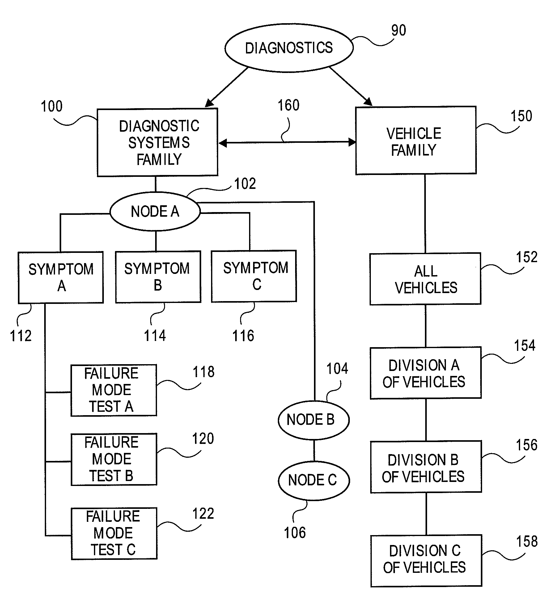
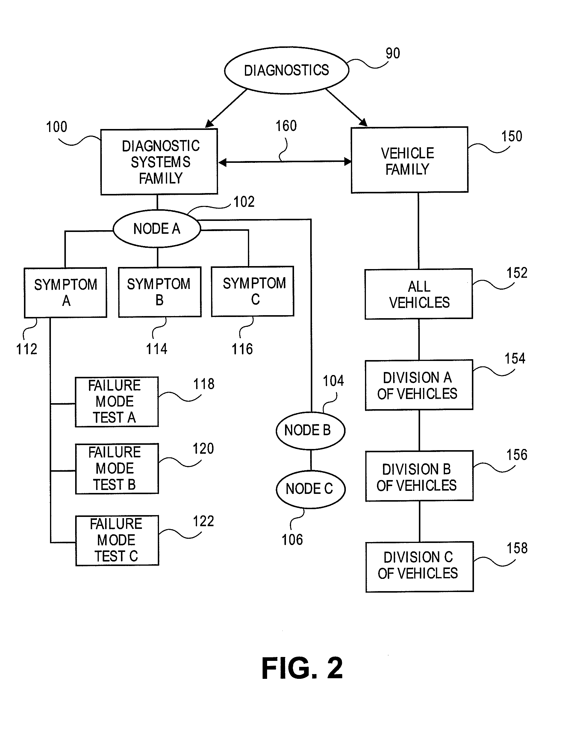
[0030]The disclosure will now be described with reference to the drawing figures, in which like reference numerals refer to like parts throughout. An embodiment in accordance with the present disclosure provides an apparatus and method that will allow a user, such as a technician, to use diagnostic equipment having a hierarchy of diagnosis to determine the nature of a problem. The diagnostic equipment can include, for example, but not limited to a diagnostic tool or a personal computer.

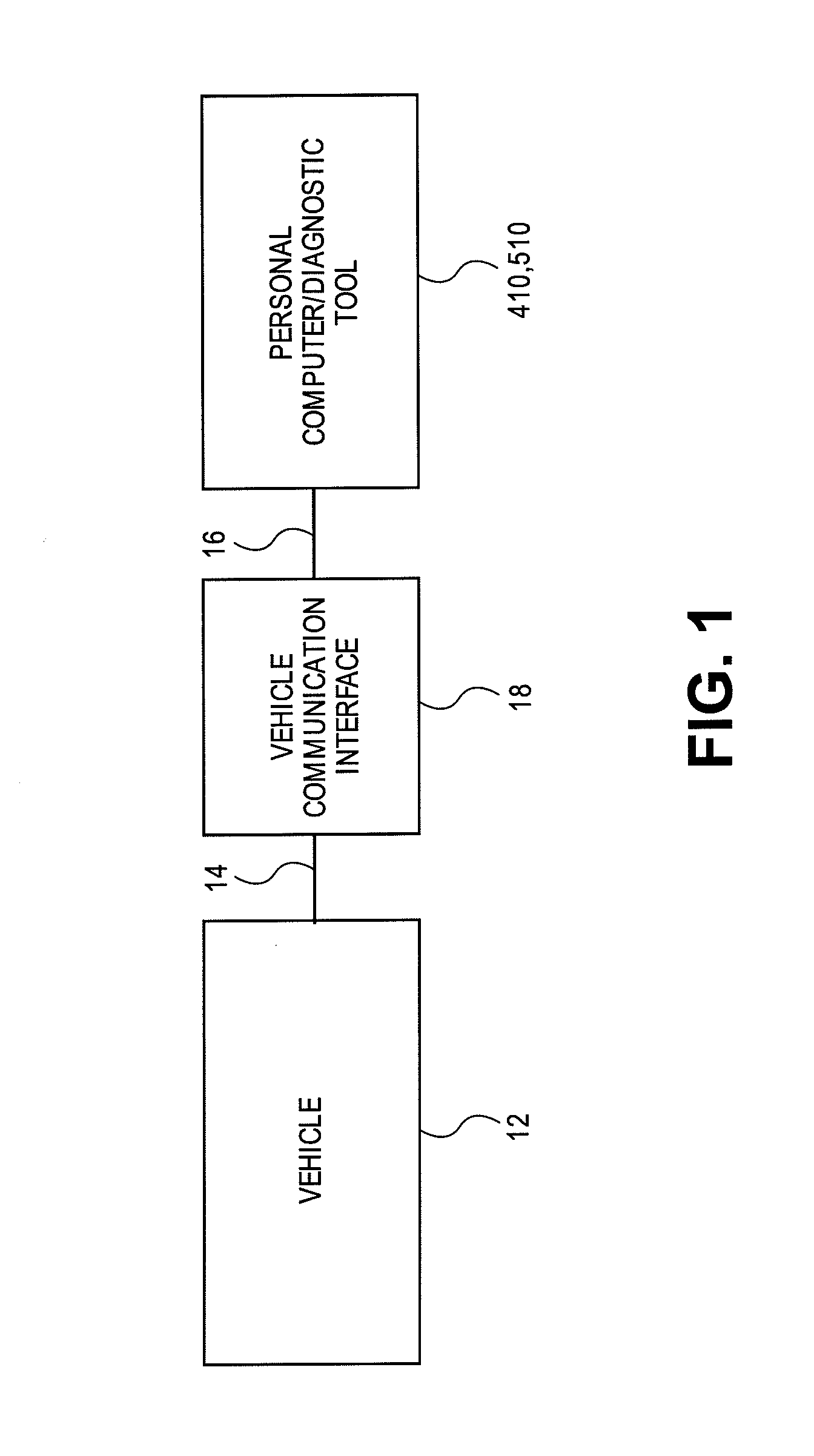
[0031]Referring to FIG. 1, a vehicle 12 is shown connected to a personal computer 410 or a dedicated diagnostic tool 510 via a vehicle communication interface 18. A first connection 14 between vehicle 12 and the vehicle communication interface 18, and a second connection 16 between the vehicle communication interface 18 and the personal computer / diagnostic tool 410 and 510 can be either wired or wireless.

[0032]Applicable communications with the host, such as a vehicle 12 connected to the diagnostic to...


PUM


Abstract

A diagnostic tool for diagnosing a vehicle, includes a signal translator that communicates with the vehicle in at least one protocol, an input device that inputs information, a processor that controls a software according to the input information from the input device and communicates with the vehicle with the signal translator, the processor controls a reception of diagnostic data of the vehicle through the signal translator, the processor receives a selected instruction of the diagnostic tool through the input device and correlates the desired instruction information with the information stored in a memory, the processor processes the received diagnostic data according to the selected instructions information according to a hierarchy stored on the memory, the memory stores the software controlled by the processor, the memory stores a database of information for use by a hierarchical grouping of criteria and tests for diagnostics, the hierarchy including a first grouping and a second grouping, with each of the first and second grouping being further subdivided into additional sub-groupings, the selection of the diagnostic test being made according to the hierarchy from the most specific grouping to the most general grouping, executing through the processor the selected diagnostic test according to the hierarchy, and a display unit that receives and displays diagnostic information according to the selected stored and processed hierarchical information.

Description

TECHNICAL FIELD[0001]The present disclosure relates generally to diagnostic equipment. More particularly, the present disclosure relates to a diagnostic hierarchy for use in a vehicle diagnostic tool.BACKGROUND OF THE DISCLOSURE[0002]Onboard control computers have become prevalent in motor vehicles, but as safety, economy, and emissions requirements have continued to tighten, friction braking systems, and traction control devices have not met the requirements set out in government regulations and the implicit demands of competitors' achievements. Successive generations of onboard control computers have acquired increasing data sensing and retention capability as the electronics have advanced.[0003]Present external diagnostic and display apparatus, known as diagnostic tools, are commonly limited to reporting the data acquired by the onboard control computer itself. Increasingly, subtle subsystem failures in vehicles overload the ability of maintenance technicians, not simply to read ...

Claims


Application Information

Patent Timeline
IPC IPC(8): G06F15/00
CPCG07C2205/02G06Q10/06
Inventor UNDERDAL, OLAV M.GILBERT, HARRY M.PORTYANKO, OLEKSIYMAYES, RANDY L.FOUNTAIN, GREGORY J.WITTLIFF, III, WILLIAM W.
Owner SPX CORP
Features
  • R&D
  • Intellectual Property
  • Life Sciences
  • Materials
  • Tech Scout
  • Unparalleled Data Quality
  • Higher Quality Content
  • 60% Fewer Hallucinations
Learn More