Apparatus and method for enhanced solar power generation and maximum power point tracking

a solar array and power generation technology, applied in the direction of electric variable regulation, process and machine control, instruments, etc., can solve the problems of continuous change of illumination conditions on the surface partial shading and/or continuous shadow conditions of the solar array, etc., to achieve the effect of maximizing the power generation of the solar array

Inactive Publication Date: 2009-09-03
UNIVERSITY OF SOUTH CAROLINA
View PDF7 Cites 203 Cited by
  • Summary
  • Abstract
  • Description
  • Claims
  • Application Information

AI Technical Summary

Benefits of technology

[0010]The present subject matter recognizes and addresses the disadvantages of prior art constructions and methods. Accordingly, it is an object of the present subject matter to provide a solar array configuration with respect to optimum solar cell size and connections to maximize the power generation of the solar array under partially shading or continuously changing shadow conditions.
[0012]Yet still a further object of the present subject matter is to provide a solar array configuration with respect to optimum solar cell size and connections to maximize the power generation of the solar array under partially shading or continuously changing shadow conditions.
[0014]To address the above objects, the present subject matter provides a solar power generation apparatus corresponding to a solar array which is formed by connecting a very limited number of solar cells in series to form a string and connecting a plurality of solar cell strings in parallel; and a power converter which is connected to said solar array to boost the solar array terminal voltage to a desired level to match the target application requirement. A solar array constructed in accordance with the present technology is capable of maximizing the power generation of each solar cell under partially shading or continuously changing shadow conditions.

Problems solved by technology

Unlike standing solar arrays mounted outdoors, portable solar arrays incorporated into solar jackets or bags may be subject to partial shading and / or continuously changing shadow conditions.
For example, when carrying a solar jacket through a city, illumination condition on the surface of the solar array changes continuously and the intensity is non-uniform across the surface due to shadows of trees, vehicles, and buildings, as well as due to change of orientation of the array relative to the sun.
Partially shaded cells generate a certain amount of energy that can not be used by classical designs where bypass diodes are used.
This arrangement, however, does not work as well for portable solar. arrays, because the operation of portable solar arrays is constantly under complex illumination conditions due to user's random movement and varying shadow conditions.
Solar arrays in portable and mobile applications are often subject to partially shading or continuously changing shadow conditions.
These complex irradiance conditions cause two problems for the solar arrays using the conventional configurations.
First, partially shaded cells generate a certain amount of energy but that energy cannot be collected by the widely used designs where bypass diodes are used, thus this part of the energy is wasted.
It is a significant problem, however, in low voltage systems for portable and mobile applications where partial shading occurs frequently and quite a fraction of cells may be partially shaded.
For example, carrying a solar jacket through a city, the illumination condition on the surface of the solar array changes continuously and the intensity is non-uniform across the surface due to shadows of trees, vehicles, and buildings, as well as due to change of orientation of the array relative to the sun.
Second, continuously changing shadow conditions increase the difficulty of the maximum power point tracking.
On the other hand, even if the maximum power tracking works well, the energy generated by partially shaded cells can not be collected, while this part of energy could be comparatively large especially when quite a number of cells are partially shaded.

Method used


Image

  • Apparatus and method for enhanced solar power generation and maximum power point tracking
  • Apparatus and method for enhanced solar power generation and maximum power point tracking
  • Apparatus and method for enhanced solar power generation and maximum power point tracking

Examples


Embodiment Construction

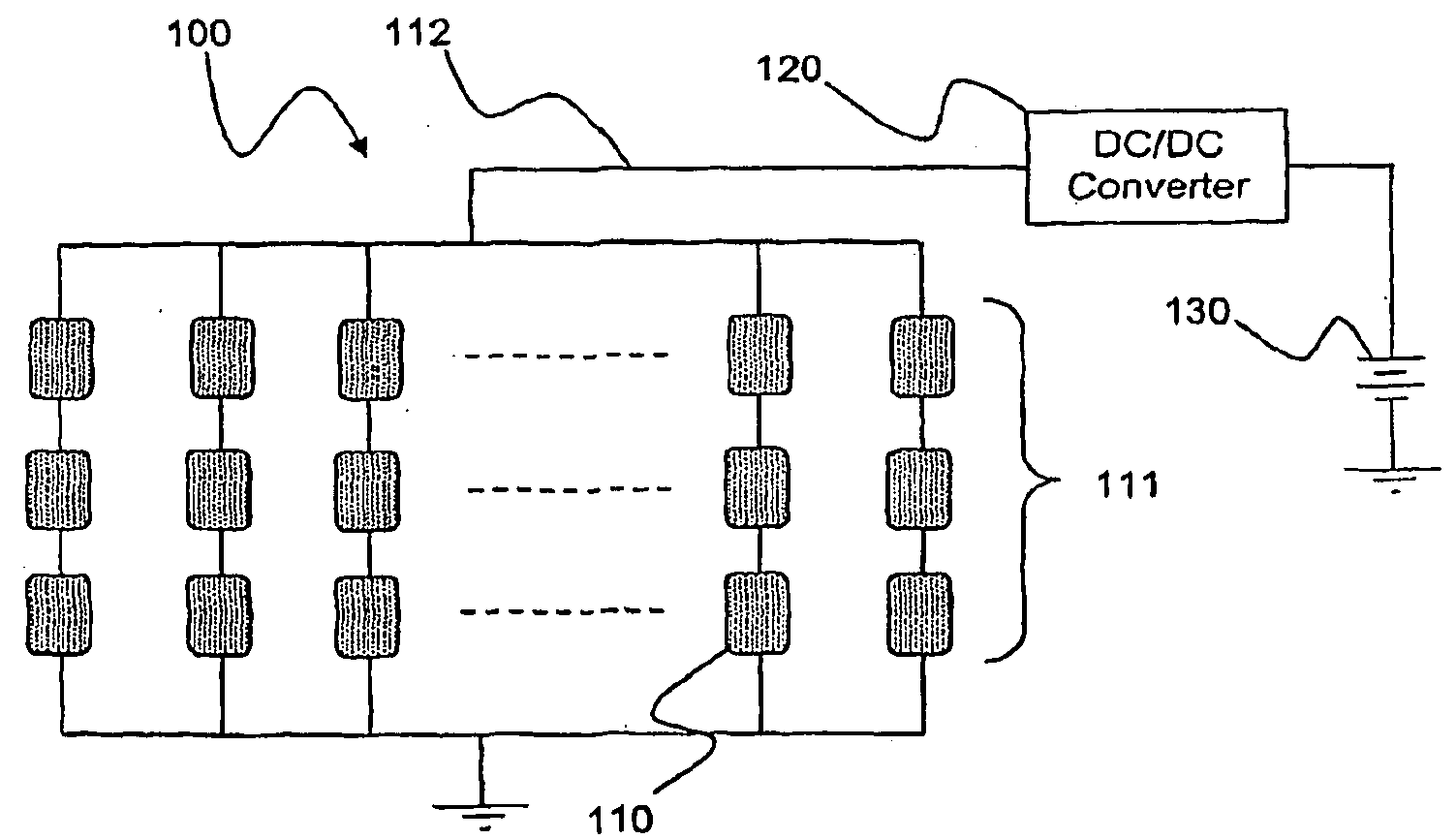
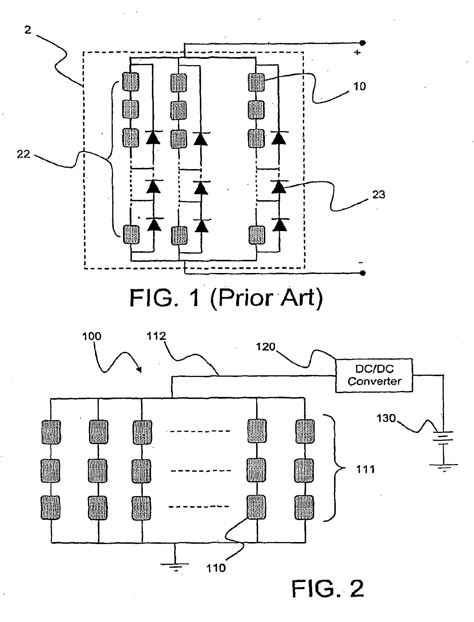
[0038]As discussed in the Summary of the Invention section, the present subject matter is particularly concerned with optimization of solar cell size and connections to maximize power generation of the solar array under partially shading or continuously changing shadow conditions.

[0039]Selected combinations of aspects of the disclosed technology correspond to a plurality of different embodiments of the present invention. It should be noted that each of the exemplary embodiments presented and discussed herein should not insinuate limitations of the present subject matter. Features or steps illustrated or described as part of one embodiment may be used in combination with aspects of another embodiment to yield yet further embodiments. Additionally, certain features may be interchanged with similar devices or features not expressly mentioned which perform the same or similar function.

[0040]Reference will now be made in detail to the presently preferred embodiments of the subject solar ...


PUM


Abstract

Disclosed is an apparatus and methodology for generating operating power for various desired applications using solar energy. A solar array is formed using a small number of solar cells connected in series to form a string of solar cells and then connecting multiple strings in parallel. Unlike conventional solar arrays, no bypass diodes are incorporated into the array. A power converter is coupled to the array to boost output voltage to a level sufficient to operate the desired application. The power converter may be operated independently or based on output levels of the array, the material from which the solar cells of the array are constructed and the operating temperature of the array or combinations thereof.

Description

CROSS-REFERENCE TO RELATED APPLICATION[0001]This application claims the benefit of U.S. Provisional Applications Ser. No. 60 / 793,784, filed on Apr. 21, 2006, and No. 60 / 833,092, Jul. 25, 2006, both of which are assigned to the assignee of the present application.STATEMENT OF GOVERNMENT INTEREST[0002]The present subject matter was developed under Grant N0014-0301-0952 from the Office of Naval Research. The government retains certain rights in this subject matter.FIELD OF THE INVENTION[0003]The present subject matter relates to a solar power generation apparatus employing a methodology for maximum power point (MPP) tracking. More particularly the present subject matter relates to a solar power generation apparatus capable of maximizing the power generation of a solar array for portable and mobile applications that are often subject to partially shading or continuously changing shadow conditions.BACKGROUND OF INVENTION[0004]Photovoltaic (PV) cells have been widely used in portable appl...

Claims


Application Information

Patent Timeline
Patent Type & Authority Applications(United States)
IPC IPC(8): H01L31/042
CPCG05F1/67Y02E10/58H01L31/042H01L31/044H01L31/0504Y02E10/56
Inventor DOUGAL, ROGER A.GAO, LIJUNLIU, SHENGYIIOTOVA, ALBENA
Owner UNIVERSITY OF SOUTH CAROLINA
Why Eureka
Try Eureka