
Drilling rig structure installation and methods

Active Publication Date: 2009-09-03
NAT OILWELL VARCO LP
View PDF69 Cites 43 Cited by
  • Summary
  • Abstract
  • Description
  • Claims
  • Application Information

AI Technical Summary

Benefits of technology

The present invention provides a system and method for installing a rig structure on a drilling rig without using a crane, winching up cables, or a drawworks to lift the structure. The system includes a movement apparatus for positioning the rig structure, a support apparatus for selectively supporting the rig structure, and a raising apparatus for raising the rig structure with the support apparatus. The invention solves the problem of using cranes and other heavy equipment to install rig structures on drilling rigs, which can be time-consuming and costly. The invention allows for a faster and safer installation process, reducing the risk of injury and damage to the rig.

Problems solved by technology

Various problems and disadvantages are associated with installing structure, e.g. a doghouse, on a rig using a crane.

Method used


Image

  • Drilling rig structure installation and methods
  • Drilling rig structure installation and methods
  • Drilling rig structure installation and methods

Examples


Embodiment Construction

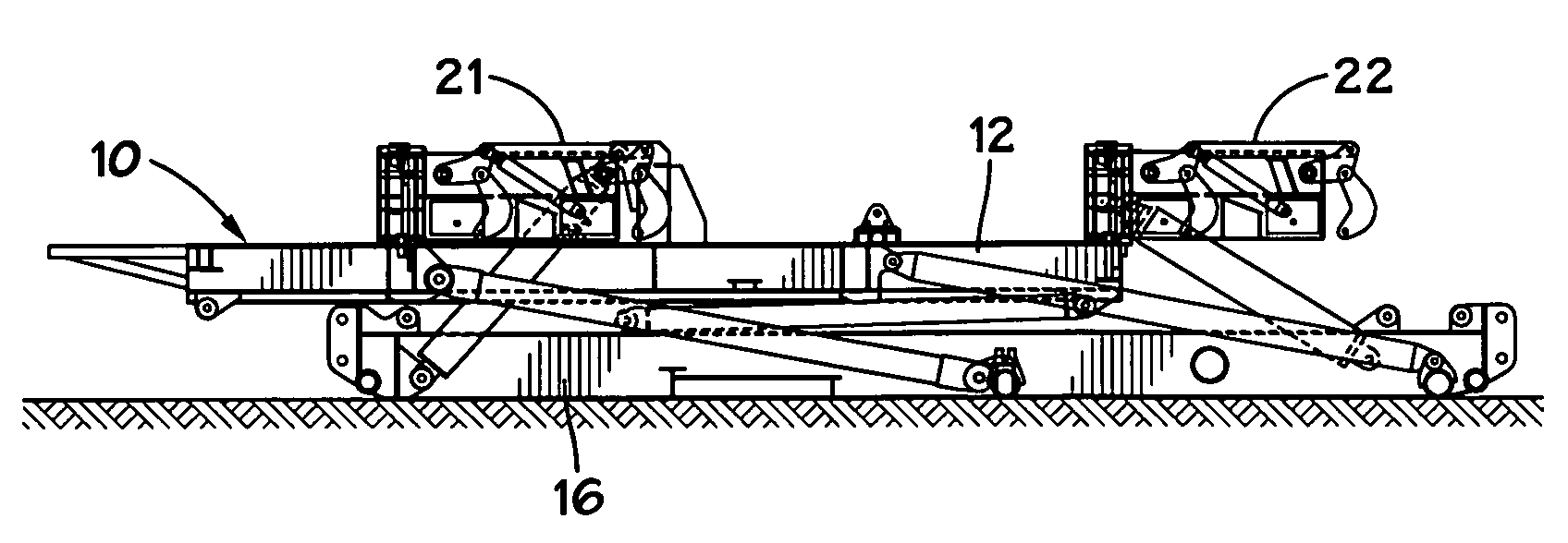
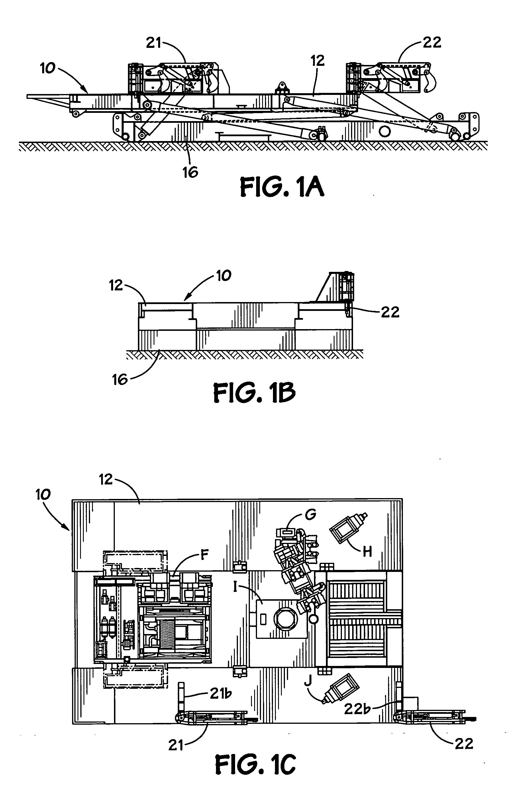
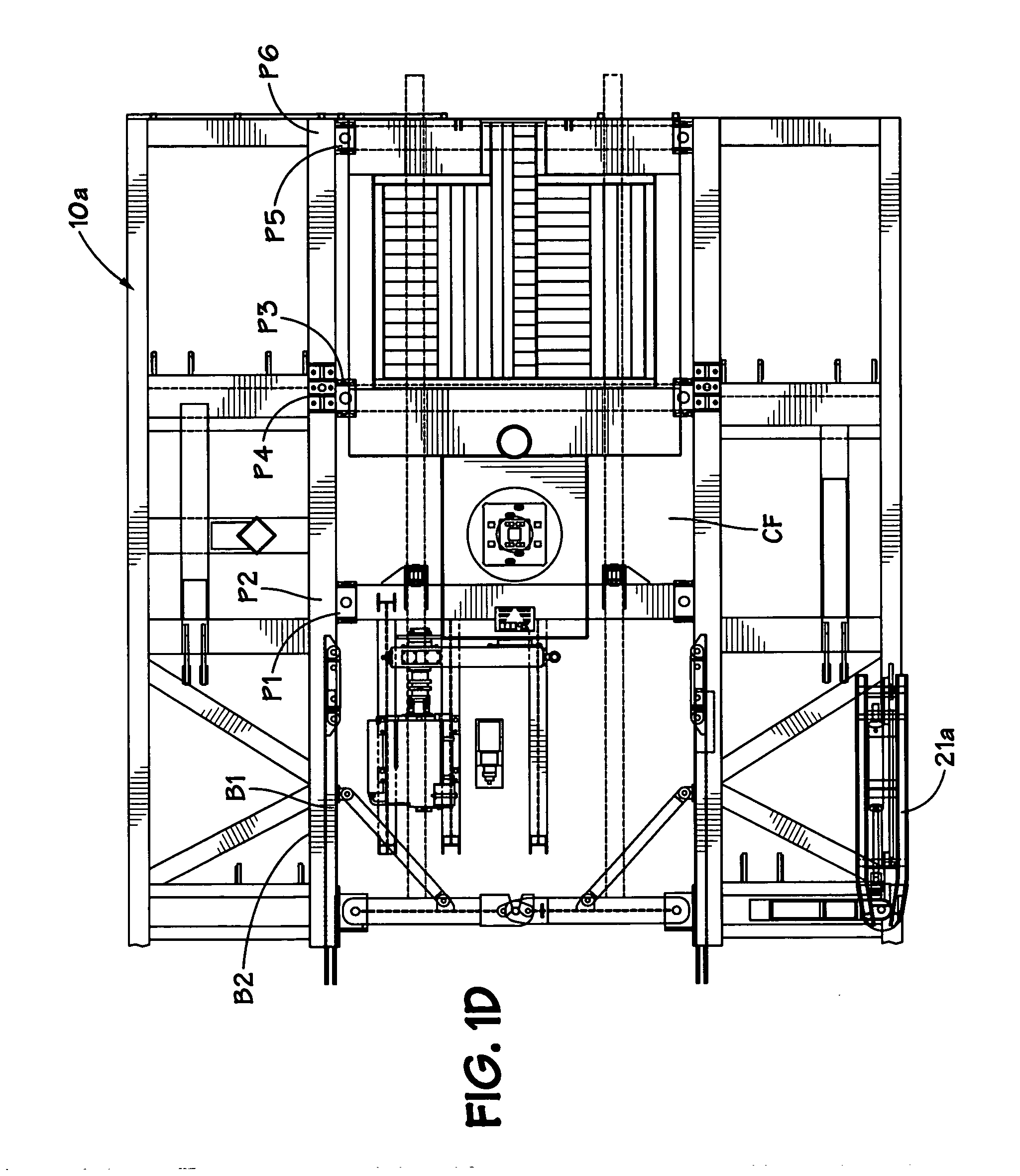
[0079]FIGS. 1A, 1B and 1C show a rig 10 with rig equipment F, G, H, I, J on a drill floor 12, the drill floor 12 is raised by a substructure 16 to which the drill floor 12 is connected. Connected to the substructure 16 is a structure lifting and movement apparatus which includes a left suspending arm 21 and a right suspending arm 22.

[0080]Each suspending arm 21, 22 (see FIGS. 2A, 2B) has support beams (see beams 21l, 21m, FIG. 2B) and is pivotably connected with pins (e.g. see pins 21c, 21d for the arm 21) to a base 21b, 22b, respectively, and these bases are secured or formed integrally of the drill floor 12. The suspending arms 21, 22 can pivot 180° on their bases. Each suspending arm has a linkage assembly raised and lowered by an hydraulic cylinder apparatus 23 (one arm at each end of the skid 17 of the structure 40). A piston 23p of each apparatus 23 movable in a housing 23h is connected to a first top link 24t. A pin 232 pivotably connects a lower end of the housing 23h to the...


PUM


Abstract

A method for installing rig structure (e.g. cabin, house, a doghouse) on a drilling rig, the method including: connecting support apparatus to a substructure of a drilling rig, supporting a drilling floor; moving a movement apparatus supporting a rig structure to position it adjacent the support apparatus, by moving movement apparatus on ground adjacent the substructure, moving the support apparatus into a connecting orientation with respect to the structure; connecting raising apparatus to the structure, the raising apparatus connected to the support apparatus; raising the structure up to the drill floor with the raising apparatus; and securing the structure to the support apparatus. This abstract is provided to comply with the rules requiring an abstract which will allow a searcher or other reader to quickly ascertain the subject matter of the technical disclosure and is submitted with the understanding that it will not be used to interpret or limit the scope or meaning of the claims, 37 C.F.R. 1.72(b).

Description

BACKGROUND OF THE INVENTION[0001]1. Field of the Invention[0002]This invention is directed to drilling rigs; drilling rigs with structure thereon such as a doghouse, driller's cabin, building, or electrical control house; and to methods for installing such structures on a rig.[0003]2. Description of Related Art[0004]The prior art discloses a variety of rigs used in drilling and various wellbore operations; for example, and not by way of limitation, U.S. Pat. Nos. 3,340,938; 3,807,109; 3,922,825; 3,942,593; 4,269,395; 4,290,495; 4,368,602; 4,489,526; 4,569,168; 4,837,992; 6,634,436; 6,523,319 and 7,306,055 and the references cited in these patents—all these patents incorporated fully herein for all purposes. The prior art discloses a variety of systems and methods for assembling and raising components of a drilling rig; for example, and not by way of limitation nor as an exhaustive listing, the disclosures in U.S. Pat. Nos. 2,993,570; 3,201,091; 3,262,237; 3,749,183; 4,221,088; 4,269...

Claims


Application Information

Patent Timeline
Patent Type & Authority Applications(United States)
IPC IPC(8): E21B7/00
CPCE21B15/00E21B7/023
Inventor DONNALLY, ROBERT BENJAMINREN, CHUNQIAOMCCURDY, STUART ARTHUR LYALLLIUI, XI LINSHENG, HUI CHUNYU, YANCHEN, HE HUI
Owner NAT OILWELL VARCO LP
Learn More