
Device and a method for control of power flow in a transmission line

Inactive Publication Date: 2009-09-03
ABB RES LTD
View PDF12 Cites 26 Cited by
  • Summary
  • Abstract
  • Description
  • Claims
  • Application Information

AI Technical Summary

Benefits of technology

[0014]In a preferred embodiment, each of the shunt trans-formers comprises a tap-changer to which the respective controllable reactance is connected. By means

Problems solved by technology

However, the use of a PST offers a slow control speed.
Thus the PST cannot participate in a decisive way in a transient period following a power disturbance.
Further frequent tap changing, in particular at high current conditions, increases the need for maintenance.
The tap-changer is a mechanical device and thus slow and an object to mechanical wear.
Small voltage steps result in a greater number of mechanical operations.
The reactive power consumption increases quadratic with the line current and is thus pronounced at high loading of the power system.

Method used


Image

  • Device and a method for control of power flow in a transmission line
  • Device and a method for control of power flow in a transmission line
  • Device and a method for control of power flow in a transmission line

Examples


Embodiment Construction

[0033]In the following a detailed description of preferred embodiments of the present invention will be given.

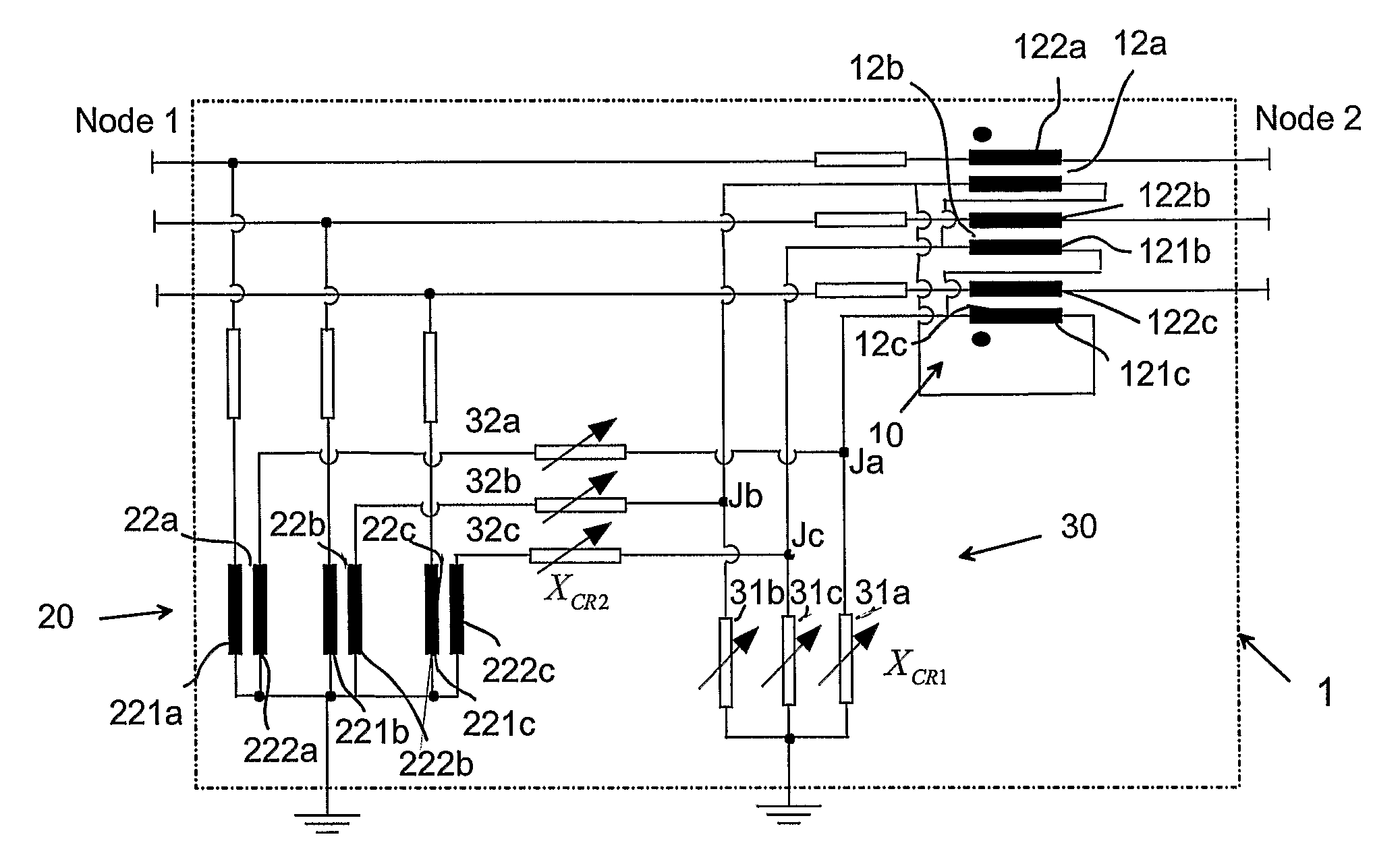
[0034]A device for controlling the power flow according to the invention, generally designated 1, is shown in FIGS. 4 and 5. The device comprises a series transformer unit 10, a shunt transformer unit 20, a controllable reactance unit 30 comprising two controllable reactances (XCR1 and XCR2) 31 and 32, and a control unit 40 controlling the reactance values of the controllable reactances. The units are adapted for three-phase operation. This means that the series transformer unit comprises three transformers 12a-c, each comprising a primary winding 121a-c and a secondary winding 122a-c. For each phase, the primary winding being adapted to be supplied with a voltage that is dependent on a controllable part of the voltage between the other two phases of the transmission line, while the secondary winding being adapted for serial connection into the respective phase of the transm...


PUM


Abstract

A device for control of power flow in a three-phase ac transmission line. The device includes a series transformer unit, a shunt transformer unit, and a reactance unit.

Description

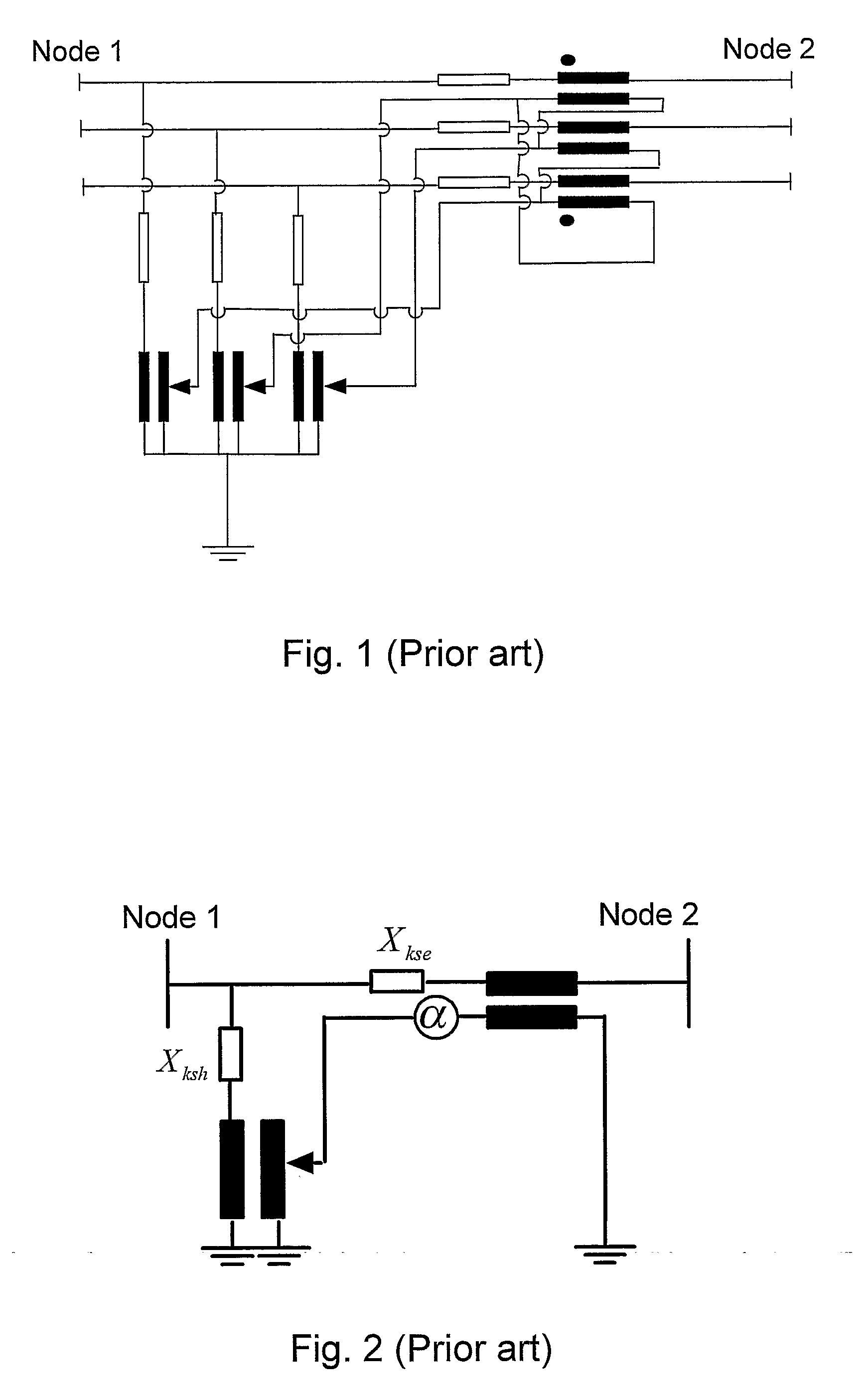
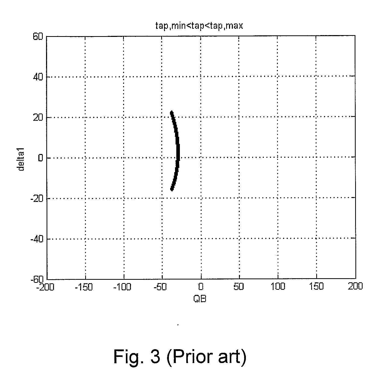
FIELD OF INVENTION[0001]The present invention relates to a device and a method for control of power flow in a three-phase transmission line.BACKGROUND[0002]Different kinds of devices for both static and dynamic control of the power flow in such a transmission line are known. The object of the control may be a static distribution of power between power lines or power networks, as well as damping of power oscillations in the transmission line.[0003]A phase shifting transformer (PST) is previously known for controlling the power flow in an ac transmission line, i.e., a three-phase ac line that interconnects two electric power networks and transmits active power between the power networks. There are a number of different previously known designs of phase-shifting transformers. FIG. 1 shows a principal circuit diagram corresponding to one such known design commonly referred to as the quadrature booster design and known from the US patent publication 6,737,837 B1. The main parts of this d...

Claims


Application Information

Patent Timeline
IPC IPC(8): G05F1/70
CPCH02J3/1828H02J3/1864Y02E40/30Y02E40/12H02J3/1878Y02E40/10
Inventor BERGGREN, BERTILNOROOZIAN, MOJTABA
Owner ABB RES LTD
Learn More